
Arduino Ohm Meter

Made by hIOTron / Productivity / IoT
About the project
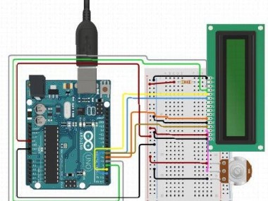
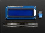
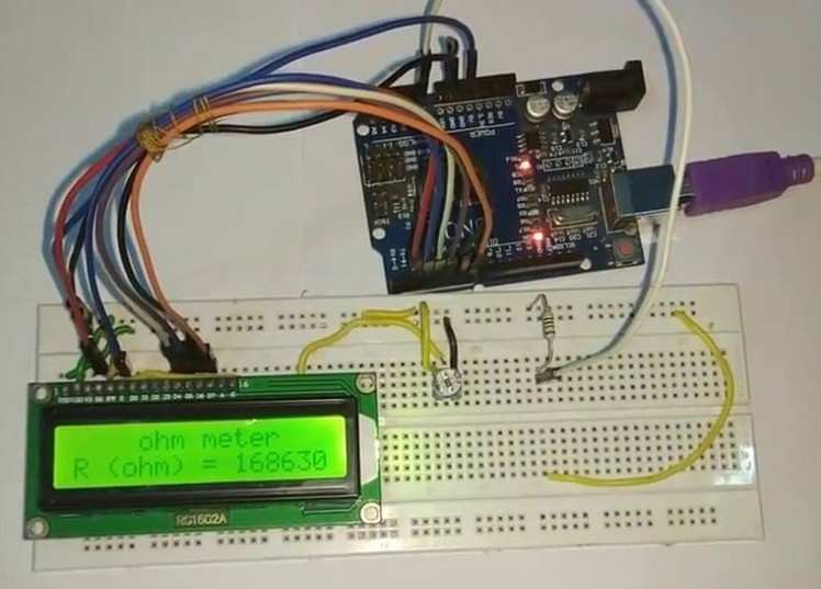
The main principle behind this is the voltage divider network. The value of the unknown resistance is displayed on the 16*2 LCD display.
Project info
Difficulty: Moderate
Platforms: Arduino
Estimated time: 1 day
License: GNU General Public License, version 3 or later (GPL3+)
Items used in this project
Hardware components


Story
About Project
The working of this Resistance Meter is very simple and can be described using a voltage divider network shown below.
From the voltage divider network of resistors R1 and R2,
Vout = Vin * R2 / ( R1+R2 )
From the above equation, we can deduce the value of R2 as
R2 = Vout * R1 / (Vin - Vout)
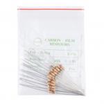
Where R1 = known resistance
R2 = Unknown resistance
Vout = voltage at R2 with respect to ground
Vin = voltage presented at the 5V pin of Arduino
So if we see the value of voltage across unknown resistance (Vout), we can clearly determine the unknown resistance R2. Here we have read the voltage value Vout using the analog pin A0 and converted those digital values (0 -1023) into voltage as explained in the Code.
If the value of the known Resistance is higher or smaller than the unknown resistance the error will be more. So it is necessary to keep the known resistance value next to the unknown resistance.
IoT Training Online will help you to build an Industrial IoT Solutions.
Code
Credits
Related products


Leave your feedback...