

Items used in this project
Hardware components

Story
Introduction to Color Sensor
The TCS3200 color sensor is a programmable color sensor that changes color light to frequency. The output frequency of the sensor is directly proportional to the intensity of the light bounced from the object.
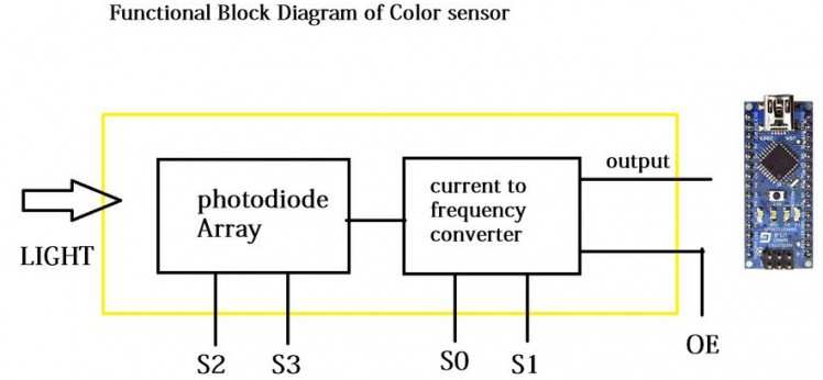
The TCS3200 Color Sensor Module has RGB + Clear Sensor along with 4 bright white LEDs embedded on the board. TCS3200 has an 8 x 8 array of photodiodes, 16 each for Red filters, Blue filters, Green filters and no filter. The block diagram of the color sensor is as follows.
It contains color filters, photodiode array, current to frequency converter and final square wave output which can be given directly to a microcontroller.
Working of Project
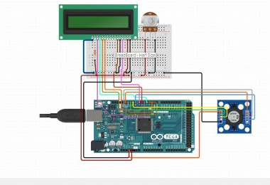
A simple Color Sensor using Arduino is generated in this project. The color sensor module senses the color in its surroundings.
As discussed in the introduction to the color sensor section, the TCS3200 Color Sensor has filters for Red, Blue, Green and Clear. The intensity of each color is reproduced as a frequency.
In Arduino, we have made the output frequency scale to 100% by applying HIGH to S0 and S1 pins of the color sensor. We have to use the S2 and S3 pin on the color sensor to select the type of photodiode i.e. red, green or blue.
Whenever a particular Photodiode is chosen, the PULSEIN feature of the Arduino is initiated on the pin that is attached to the output of the Color Sensor.
This will assist us to estimate the frequency of the output signal. The same process is replicated for all the three photodiodes: R, G and B. The frequency in all the cases is calculated using the PULSEIN feature and is presented on the Serial Terminal.
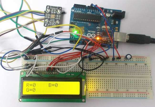
Additionally, this information can be utilized to recognize the color placed in front of the sensor and display its color on the LCD and also light up the corresponding LED.
Learn more about IoT Training and learn how to build and develop various Industrial IoT Solutions.
Code
Credits
Related products


Leave your feedback...