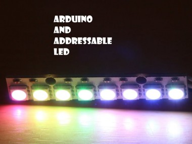
Arduino and Addressable LED
About the project
Because LED are fun - but addressable rocks. :)
Project info
Difficulty: Easy
Estimated time: 1 hour
License: GNU General Public License, version 3 or later (GPL3+)
Items used in this project
Story
I really love LED, and more then all addressable.
The main reason is there ease of use, power and one data cable only and you got as (almost) many RGB LED as you like.
The code can not be easier with the use of the FastLed library.
You can install it very easily with the use of the library manger within your IDE, I cover the process in the video.
Great reference to the library
http://fastled.io/docs/3.1/index.html
https://github.com/FastLED/FastLED/wiki/API-Reference
I cover 2 codes, the first one is the example code of the blink.
#include "FastLED.h"
// How many leds in your strip?
#define NUM_LEDS 8
// For led chips like Neopixels, which have a data line, ground, and power, you just
// need to define DATA_PIN.  For led chipsets that are SPI based (four wires - data, clock,
// ground, and power), like the LPD8806 define both DATA_PIN and CLOCK_PIN
#define DATA_PIN 3
#define CLOCK_PIN 13
// Define the array of leds
CRGB leds[NUM_LEDS];
void setup() {
     // Uncomment/edit one of the following lines for your leds arrangement.
     // FastLED.addLeds<TM1803, DATA_PIN, RGB>(leds, NUM_LEDS);
     // FastLED.addLeds<TM1804, DATA_PIN, RGB>(leds, NUM_LEDS);
     // FastLED.addLeds<TM1809, DATA_PIN, RGB>(leds, NUM_LEDS);
     // FastLED.addLeds<WS2811, DATA_PIN, RGB>(leds, NUM_LEDS);
     // FastLED.addLeds<WS2812, DATA_PIN, RGB>(leds, NUM_LEDS);
     // FastLED.addLeds<WS2812B, DATA_PIN, RGB>(leds, NUM_LEDS);
 	  FastLED.addLeds<NEOPIXEL, DATA_PIN>(leds, NUM_LEDS);
     // FastLED.addLeds<APA104, DATA_PIN, RGB>(leds, NUM_LEDS);
     // FastLED.addLeds<UCS1903, DATA_PIN, RGB>(leds, NUM_LEDS);
     // FastLED.addLeds<UCS1903B, DATA_PIN, RGB>(leds, NUM_LEDS);
     // FastLED.addLeds<GW6205, DATA_PIN, RGB>(leds, NUM_LEDS);
     // FastLED.addLeds<GW6205_400, DATA_PIN, RGB>(leds, NUM_LEDS);
     // FastLED.addLeds<WS2801, RGB>(leds, NUM_LEDS);
     // FastLED.addLeds<SM16716, RGB>(leds, NUM_LEDS);
     // FastLED.addLeds<LPD8806, RGB>(leds, NUM_LEDS);
     // FastLED.addLeds<P9813, RGB>(leds, NUM_LEDS);
     // FastLED.addLeds<APA102, RGB>(leds, NUM_LEDS);
     // FastLED.addLeds<DOTSTAR, RGB>(leds, NUM_LEDS);
     // FastLED.addLeds<WS2801, DATA_PIN, CLOCK_PIN, RGB>(leds, NUM_LEDS);
     // FastLED.addLeds<SM16716, DATA_PIN, CLOCK_PIN, RGB>(leds, NUM_LEDS);
     // FastLED.addLeds<LPD8806, DATA_PIN, CLOCK_PIN, RGB>(leds, NUM_LEDS);
     // FastLED.addLeds<P9813, DATA_PIN, CLOCK_PIN, RGB>(leds, NUM_LEDS);
     // FastLED.addLeds<APA102, DATA_PIN, CLOCK_PIN, RGB>(leds, NUM_LEDS);
     // FastLED.addLeds<DOTSTAR, DATA_PIN, CLOCK_PIN, RGB>(leds, NUM_LEDS);
}
void loop() {
 // Turn the LED on, then pause
 leds[0] = CRGB::Red;
 FastLED.show();
 delay(500);
 // Now turn the LED off, then pause
 leds[0] = CRGB::Black;
 FastLED.show();
 delay(500);
}
Its a very simple code that will make the first LED blink in red.
I then cover the work on this example, and how easy it is to change the patterns and the refresh action of the LED. code is attached in the main
Few important things I learned since making that video while back, and the majority of it was due to this project :
1. If you are powering many LED, Like I did, make sure the strip is fully powered before trying to "talk to it". I kept on burning one of the first 4-5 LED of the project, and it was due to very fast load on the MCU (attiny85) and not fast enough on the power line. the difference of voltage kept on damaging them. the solution was to add a delay on setup of about 500 millis before trying to communicate with the strip.
2. the data line can not be more then 1 meter long, especially if your have a long strip. try to have the data in line as close as possible to the strip. In this project I had the rpi control the strip and when I had to extend the length of the cable, due to the physical distance, the communication kept on messing up and the LED will get random lights patterns. ended up moving the control of the LED strip to a attiny85 that was triggered by the rpi.
3. make sure to add a capacitor, on the power line as close as possible to the strip it self, to give you that extra balance of power.


Leave your feedback...