
7 Segment Display Clock With Max7219 And Ds1307 Rtc

About the project
Make a 7 Segment digital clock with MAX7219 and DS1307 Real Time Clock (RTC) - Quick and Easy!
Project info
Difficulty: Easy
Estimated time: 1 hour
License: GNU General Public License, version 3 or later (GPL3+)
Items used in this project
Hardware components

Software apps and online services
Story
DS1307 Real Time Clock are widely available low cost I2C RTC modules. They come with a clock and a small battery and, when connected to Arduino, can keep track of real time even when the Arduino board is not powered. I already made a tutorial on how to use them with Arduino Nano. Some of you have asked how you can display the time with LED Display.
In this Tutorial, I will show you how to connect DS1307 I2C RTC Module and the MAX7219 controlled 7 Segment LED Display to Arduino, read and display the time, and program all this with Visuino. I will use the Tiny RTC Module that I have, but it should be very much the same with any other DS1307 Module.
Step 1: Components
1 / 2 • Picture 1

Picture 1

Picture 2
- One Arduino compatible board (I use Arduino Nano, because I have one, but any other will be just fine)
- One DS1307 Real Time Clock Module (I used Tiny RTC Module but any other DS1307 Module will be just fine)
- One 8 digits 7 Segment Display module with MAX7219 controller (Picture 2 shows the backside of the module with the MAX7219 controller)
- One small Breadboard (Any breadboard can be used, or any other way to connect 3 wires together)
- 3 Female-Male jumper wires
- 7 Female-Female jumper wires
1 / 4 • Picture 1

Picture 1

Picture 2
- Connect the Female end of a Female-Male 5V VCC Power (red wire) to the DS1307 RTC Module (Picture 1)
- Connect Female-Female wires - Ground (black wire), SCL (orange wire), and SDA (blue wire), to the DS1307 RTC Module (Picture 1)
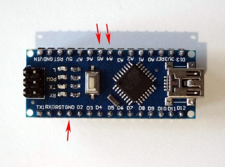
- Connect the other end of the SDA wire (blue) to SDA/Analog pin 4 of the Arduino Nano board (Picture 2)
- Connect the other end of the SCL wire (orange) to SCL/Analog pin 5 of the Arduino Nano board (Picture 2)
- Connect the other end of the Ground wire (black) to Ground pin of the Arduino Nano board (Picture 3)
- Picture 4 shows where are the Ground, SDA/Analog pin 4, and SCL/Analog pin 5, pins of the Arduino Nano
1 / 4 • Picture 1

Picture 1

Picture 2

Picture 3

Picture 4
- Connect the Female end of a Female-Male 5V VCC Power (red wire) to the LED Module (Picture 1)
- Connect Female-Female wires - Ground (black wire), DIN (green wire), CS (gray wire), and CLK (yellow wire) to the LED Module (Picture 1)
- Connect the other end of the Ground wire (black) to Ground pin of the Arduino Nano board (Picture 2)
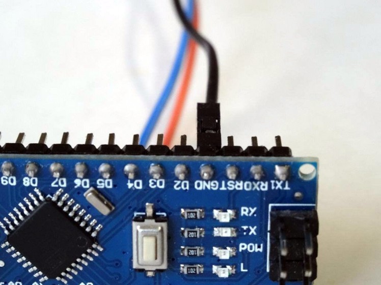
- Connect the other end of the DIN wire (green) to the Digital 11 pin of the Arduino Nano board (Picture 4)
- Connect the other end of the CS wire (gray) to the Digital 10 pin of the Arduino Nano board (Picture 4)
- Picture 5 shows In Red where are the Ground, Digital 10, 11, and 13, pins of the Arduino Nano. In Blue are shown the connections done in the previous step
1 / 3 • Picture 1

Picture 1

Picture 2

Picture 3
- Connect another Female-Male Power wire (red wire) to the 5V Power pin of the Arduino board (Picture 1), and leave the Male end unconnected
- Connect the Male ends of the 3 Power wires (red wires) - from the Display, the Clock Module, and the Arduino together as example with the help of a Breadboard (Picture 2) - In my case I used a small Breadboard
- Picture 3 shows In Red where is the 5V Power, pin of the Arduino Nano. In Blue are shown the connections done in the previous steps.
1 / 2 • Picture 1

Picture 1

Picture 2
To start programming the Arduino, you will need to have the Arduino IDE installed from here: http://www.arduino.cc/.
Please be aware that there are some critical bugs in Arduino IDE 1.6.6.
Make sure that you install 1.6.7 or higher, otherwise this Tutorial will not work!
The Visuino: https://www.visuino.com also needs to be installed.
- Start Visuino as shown in the first picture
- Click on the "Tools" button on the Arduino component (Picture 1) in Visuino
- When the dialog appears, select "Arduino Nano" as shown in Picture 2
1 / 3 • Picture 1

Picture 1

Picture 2

Picture 3
- Type "led" in the Filter box of the Component Toolbox then select the "Maxim Led Controller SPI MAX7219/MAX7221" component (Picture 1), and drop it in the design area
- Connect the "Out" pin of the LedController1 component to the to the "In" pin of the SPI channel of the Arduino component (Picture 2)
- Connect the "ChipSelect" pin of the LedController1 component to the "Digital" input of the "Digital[ 10 ]" channel of the Arduino component (Picture 3)
1 / 4 • Picture 1

Picture 1

Picture 2

Picture 3

Picture 4
The LedController1 component can control LEDs in many different ways. How the LEDs are organized and controlled depends on what Elements will be added to the component. Here we will add 3 Integer elements each with 2 digits and 2 Unsigned Bit Pixel elements. The time will be displayed in the integer elements, and the bit pixels elements will be used for the separators between hours, minutes, and seconds.
- Click on the "Tools" button of the LedController1 component (Picture 1) to open the elements editor
- In the "Elements" editor, select the "Integer Display 7 Segments" on the right, and click on the "" button on the left to add one element to the component (Picture 2)
- In the Object Inspector, set the value of the "CountDigits" property of the newly added "Integer Display 7 Segments1" element to 2 (Picture 3)
- In the Object Inspector, set the value of the "LeadingZeroes" property of the newly added "Integer Display 7 Segments1" element to "True" (Picture 4)
1 / 4 • Picture 1

Picture 1

Picture 2

Picture 3

Picture 4
- In the "Elements" editor, select the "Unsigned Bit Pixels" on the right, and click on the "" button on the left to add one element to the component (Picture 1)
- In the Object Inspector, set the value of the "CountPixels" property of the newly added "Unsigned Bit Pixels1" element to "8" (Picture 3)
- In the Object Inspector, set the value of the "InitialValue" property of the newly added "Unsigned Bit Pixels1" element to "1" (Picture 4). This will make the "-" (g) segment only active on the 7 segment digit
- Repeat the same steps from this and the previous Step 7 of the Tutorial to add 2 more "Integer Display 7 Segments" elements, and one more "Unsigned Bit Pixels" element, and set their properties the same way (Picture 4)
- Close the "Elements" editor
1 / 5 • Picture 1

Picture 1

Picture 2

Picture 3

Picture 4

Picture 5
We need to decode the Date/Time into separate Hour, Minute, and Second values. For this we will use "Decode Date/Time" component.
- Type "decode" in the Filter box of the Component Toolbox then select the "Decode Date/Time" component (Picture 1), and drop it in the design area
- Connect the "Out" pin of the RealTimeClock1 to the "In" pin of the DecodeDateTime1 (Picture 2)
- Connect the "Second" pin of the "Out" pin list of the DigitalToUnsigned1 to the "In" pin of the "PixelGroups.Integer Display 7 Segments1" element of the LedController1 component (Picture 3)
- Connect the "Minute" pin of the "Out" pin list of the DigitalToUnsigned1 to the "In" pin of the "PixelGroups.Integer Display 7 Segments2" element of the LedController1 component (Picture 4)
- Connect the "Hour" pin of the "Out" pin list of the DigitalToUnsigned1 to the "In" pin of the "PixelGroups.Integer Display 7 Segments3" element of the LedController1 component (Picture 5)
1 / 2 • Picture 1

Picture 1

Picture 2
To animate the "-" separator segments between the Hours, Minutes, and the Seconds, we will switch between "8", and "1" unsigned values every second. To do this we can use a Flip-Flop. The most convenient for this purpose is the Toggle(T) Flip-Flop:
- Type "flip" in the Filter box of the Component Toolbox then select the "Toggle(T) Flip-Flop" component (Picture 1), and drop it in the design area
- Connect the "Out" pin of the RealTimeClock1 to the "In" pin of the TFlipFlop1 component (Picture 2)
1 / 5 • Picture 1

Picture 1

Picture 2

Picture 3

Picture 4

Picture 5
The Flip flop generates a Digital(Boolean) value. We need to convert it to unsigned values of "8", and "1". To do this we will use "Digital To Unsigned" converter:
- Type "digital" in the Filter box of the Component Toolbox then select the "Digital To Unsigned" component (Picture 1), and drop it in the design area
- In the Object Inspector, set the value of the "FalseValue" property of the DigitalToUnsigned1 element to "8" (Picture 2)
- Connect the "Out" pin of the TFlipFlop1 to the "In" pin of the DigitalToUnsigned1 component (Picture 3)
- Connect the "Out" pin of the DigitalToUnsigned1 to the "In" pin of the "PixelGroups.Unsigned Bit Pixels1" element of the LedController1 component (Picture 4)
- Connect the "Out" pin of the DigitalToUnsigned1 to the "In" pin of the "PixelGroups.Unsigned Bit Pixels2" element of the LedController1 component (Picture 5)
1 / 2 • Picture 1

Picture 1

Picture 2
- In Visuino, Press F9 or click on the button shown on Picture 1 to generate the Arduino code, and open the Arduino IDE
- In the Arduino IDE, click on the Upload button, to compile and upload the code (Picture 2)
1 / 2 • Picture 1

Picture 1

Picture 2
Congratulations! You have made an LED clock with 7 Segments MAX7219 LED Display driver, and DS1307 Real Time Clock (RTC).
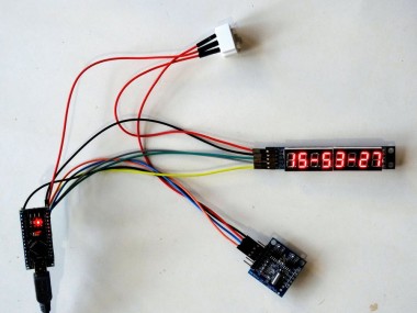
Picture 1, and the Video show the connected and powered up project.
If you power Arduino, you will see the time displayed on the 7 Segment Display.
On Picture 2 you can see the complete Visuino diagram.
Also attached is the Visuino project, that I created for this Tutorial. You can download and open it in Visuino: https://www.visuino.com
Credits
Related products


Leave your feedback...