
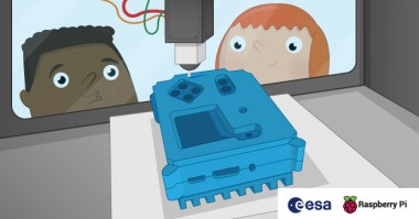
3d-printed Astro Pi Flight Case
Made by Raspberry Pi / 3D Printing / Astronomy
About the project
The Astro Pi flight case is one of the most sought-after cases in the history of the Raspberry Pi. You will learn how to 3D print your own case and install the Astro Pi hardware inside it.
Project info
Difficulty: Easy
Platforms: Raspberry Pi
Estimated time: 1 day
License: Creative Commons Attribution CC BY version 4.0 or later (CC BY 4+)
Items used in this project
Hardware components


Hand tools and fabrication machines
Story
Get the 3D files
The 3D files are in STL format, which is widely used in 3D printing all over the world. The software for your 3D printer will have no problem loading them. Import using metric millimetres (mm), and no scale adjustments will be required.
You can choose between printing using the standard STL file or the anti-warping STL file for each component. The anti-warping files add extra scaffolding around the case print to prevent the part becoming warped as it cools.
Print one file from each section:
Part 1 - Heat sink
Part 2 - Base
- Base for Model B+ or Model 2 or Anti-warp base for Model B+ or Model 2
- Base for Model 3 or Anti-warp base for Model 3
Part 3 - Middle
Part 4 - Lid
- Lid 10mm or Anti-warp lid 10mm - 10mm holes, for use with the APEM buttons
- Lid 7mm or Anti-warp lid 7mm - 7mm holes, for use with the buttons from the components kit bag in the ESA branded Astro Pi kits. Sold separately by CPC.
- Lid 3mm or Anti-warp lid 3mm - 3mm pilot holes, for drilling to fit any button size
Part 5 - Joystick cap
Note that this joystick cap may need some slight adjustments due to the nozzle size and layer height of your printer. If you have difficulty with fitting it onto the stump of the Sense HAT joystick then try using a layer height of 0.1mm as opposed to 0.15mm.
The 3D files don’t exactly match those used to make the aluminium flight cases on the International Space Station. They have been modified to make them compatible with 3D printers, so that most people who attempt this will achieve success without difficulty.
Most importantly, the case has been sliced into four parts. This has been done to minimise the amount of rafting and scaffolding that needs to be printed along with the model. It also reduces the amount of time you spend cleaning up the final prints.
Print each part
It is important that you observe the correct safety procedures specified in the data sheet for your specific 3D printer.
Potential hazards include:
- Hot surfaces and thermoplastics (print head block and lamp)
- Ultraviolet radiation (lamp)
- High voltage (lamp connector, electric outlet)
- Moving parts (printing assembly)
The 3D printer we used for the black parts shown was an Up Plus 2, called the Afinia H480 in the US, using ABS filament. There are many different 3D printer models, and we cannot possibly provide instructions for them all. We can only provide rough guidance here, and you’ll need to figure out the rest on your own.
Here are some top tips:
- Spend some time making sure your printer is properly calibrated and tested
- PLA is more reliable and nicer to print with than ABS
- A Zebra or Buildtak plate provides a great surface to print on and doesn’t require any extra adhesive
- If your printer has a Z probe sensor, this will help compensate for the bed not being perfectly level — if you have one, ensure it’s working correctly
In order to get a nice finish we recommend you print on a high detail setting; this is usually a number specified in microns in the 3D printer software. The lower this number is, the more precise the model will be. Please also be aware that precise prints take longer and, for the models you’re going to make, each piece can take up to four hours to complete. Make sure you have enough filament.
The STL files should have the models in the right orientation by default, but please make sure you print in the orientations shown below in order to minimise scaffolding and rafting.
Heat sink

Base

Middle

Lid

Remove the scaffolding
In order to keep the model structurally sound while printing, your 3D printer will create what’s called scaffolding and rafting to prevent the hot thermoplastics from bending or sagging. Leave the print to cool right down to room temperature before you touch it.
Heat sink
You should be able to remove the scaffolding on the heat sink using just your hands; this part may bend slightly, so don’t be too rough while you are removing the unwanted material.

You may choose to not print this part because it’s not essential to the rest of the case, and because it’s made of plastic it will not work as a heat sink. We’ve included it, though, so that you can achieve the iconic look and feel of the Astro Pi flight case.
Base
Like the heat sinkt, the base scaffolding should come away easily.

If you break off some scaffolding by accident, carefully prise up the remaining scaffolding using a scalpel and then continue peeling it off with your fingers.

Don’t worry if you scuff the surface with the scalpel, as the rough side of the print will not be visible when the case is assembled.
Don’t forget to clear the material around the SD card slot; this can be done easily using pliers.

Middle
Again, the scaffolding should come away easily if you peel it with your fingers.

Lid
Peel off the bottom layer of scaffolding as before.

However, this part has a few sunken holes on the underside that must also be cleared of material. These are present to prevent the lid from striking the Raspberry Pi hardware when it is installed in the case. You’ll need a scalpel or craft knife to dig into it.

Once you’ve managed to lift some of it, use a small pair of pliers to remove the rest of the material. The areas marked with a red star in the image below need the same treatment.

When you’re done, it should look like this:

Do a fit check
Before proceeding, put all the pieces together to check that they fit correctly. The lipped edge between the base and middle pieces is of most concern to you here. The heat sink and lid just need to line up.

Don’t worry about any imperfections or residue from the scaffolding at this stage; you can tidy this up later with sandpaper.
Parts checklist
Alongside your 3D-printed parts, check that you have all of the other parts required before you start:


If you’re planning to build a full Astro Pi flight unit, you can purchase a kit containing the required components from CPC.
Full list of kit parts


The kit already contains buttons, but if you want to buy the exact buttons used in the Astro Pi flight unit, the details are below. At a price of £9 each, they are expensive — that’s because they’re designed to survive an enormous number of clicks before wearing out, a feature which is necessary for a seven-year space mission.
- Manufacturer: APEM
- Manufacturer Part No: 104350003
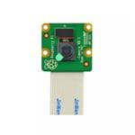
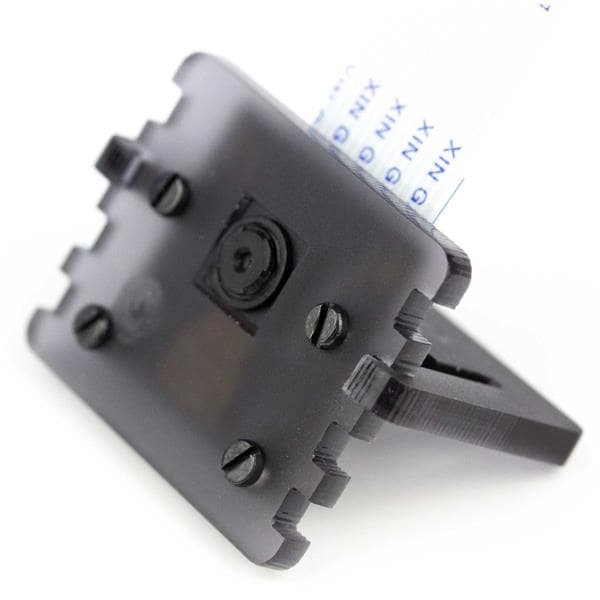
Install the camera
When you’re happy with the 3D-printed parts, you can proceed to the hardware installation.
Getting the camera into the case can be a little tricky, but here is how we did it for the flight units:
- Firstly, lift the two tabs on either side of the Camera Module to disconnect the ribbon cable from the camera.
Then fold the ribbon. These folds allow the camera cable to come up the side of the Raspberry Pi with enough flex to insert into the CSI camera port (see further down).
- Lay the ribbon out with the writing face up and the visible connectors on the left. At 1cm along the ribbon, fold the ribbon downwards.

- Now measure 4cm from the top of the ribbon and fold the ribbon to the right.

- Finally, measuring 4cm from the bottom-left corner, fold the ribbon upwards.

- Tape the ribbon on the bottom to prevent it from unfurling. We have used Kapton tape, but any kind of tape will work fine.

You don’t need to get this perfect for it to work, but try to do it as precisely as you can.
- Reconnect the Cam end of the ribbon cable to the Camera Module. Make sure that the tin connectors are facing the front and the blue tab is on the back.
- Before proceeding, line the Camera Module up with the support pillar pilot holes and have a look through the aperture in the base to check the alignment of the lens. The lens block of the Camera Module is actually glued in position at the factory, and therefore its alignment can vary slightly from camera to camera. If you find you’ve got an alignment issue, you should be able to manipulate the lens block between finger and thumb before you install it into the case permanently.
- When you’re happy, use the small black M2 cross-head screws to install the Camera Module. The screws will cut their own thread in the support pillar pilot holes, but after a few turns you’ll probably need a small screwdriver to continue.

Stop turning as soon as the head of the screw touches the Camera Module; if you tighten the screw too much, it can cause the support pillar to split horizontally along the grain of the print. Furthermore, try to avoid removing and re-threading the screws, as doing so will cut a new thread and, if done repeatedly, will erode the inside of the support pillar so that the screws will not hold.
Install the Raspberry Pi
- Firstly, ensure there’s no residual scaffolding material around the SD card slot or LED holes that might prevent the Raspberry Pi from lining up with the mounting pillars.
- Once you’re happy, line the Raspberry Pi up and do a fit check. Verify that it doesn’t touch the Camera Module below it. Don’t insert the camera ribbon cable just yet, as this will make the next job awkward.

- Next, screw the M2.5 11mm stand-offs into each corner of the Pi. With some light finger pressure they will cut their own thread in the support pillar pilot holes. After a few turns you’ll need to use a small pair of pliers to continue turning them. Try to get the stand-offs to go into the support pillars straight down, and not at a slight angle, because that can lead to alignment issues with the Sense HAT later on. Be careful while you do this and, again, stop turning as soon as the stand-off touches the Raspberry Pi to avoid splitting the pillars horizontally along the grain of the print.
If you are having trouble screwing in the stand-offs, screw one of the silver M2.5 cross-head screws into the stand-off, then use the screw head to screw the stand-off into the case. Once the stand-off is in place, don’t forget to remove the screw.

- You can now insert the camera ribbon cable into the CSI port of the Raspberry Pi. Try to make sure the tin connectors are all level to ensure a good connection.
Install stand-offs for the Sense HAT
This is where we’re going to deviate from what’s inside the Astro Pi flight unit. The flight units have another circuit board in between the Raspberry Pi and Sense HAT which holds a real-time clock, an oscillator crystal, and a backup battery. This RTC board also has some pins with six connected push-buttons. Unfortunately, the board is not available to the public.
Our goal was to keep the 3D-printed flight case as faithful to the original as possible, so the decision was taken to not alter it to accommodate the absence of this board. It may be possible for us to release the Gerber files for it in the future, so that people can make their own. We’re going to use hex nuts of the same depth as the RTC board to compensate for its absence.
- Add the extended 23-way pin header to the Raspberry Pi GPIO pins, at the end away from the USB ports.
- Then, take an 8mm M2.5 stand-off and put a hex nut onto its thread before screwing it into the hole of the 11mm stand-off, as shown below. Do the same for the remaining three stand-offs.

WARNING

A note for Pi 3 users. Using a metal stand-off next to the wireless antenna will degrade its performance and range. The advice is to either omit this stand-off from your build, or to use a nylon stand-off and nylon screw instead.
- Do not install the Sense HAT yet, as it will get in the way when you connect the GPIO pins to the buttons.
Install the push-buttons
This section assumes you are using the buttons from the Astro Pi components kit from CPC. If you are using APEM buttons or another type of button, their installation might be different.
- Take a button, then unscrew and remove the nut. Sometimes the nut will get stuck on the button cap, but it should come off if you wiggle it.

- Keeping the washer on the thread, insert the button from the underside of the lid.
- Then on the top side of the lid, put the nut back on and tighten it with your fingers. Check that the connectors are aligned horizontally on the underside before tightening fully.

- Do the same for the remaining buttons; when you are done it should look like this:

If you are using the lid with the pilot holes, then you’ll need to check the datasheet for your chosen button type to find the threaded bushing diameter. Then you can select a drill bit with this diameter, plus 1mm for clearance, and proceed to drill all six holes. We recommend using a vice or a G clamp to hold the lid in place while you drill. You can then install the buttons in accordance with their requirements.
Create the button wires
Firstly, you need to prepare the button wires to be able to attach them to the buttons. In the real flight unit, we soldered the button wires on to make them more reliable — in the kit you will find jumper wires which will do the same job. The colour of the wires is not important, as they are all exactly the same inside.
- Take a coloured wire and, without cutting it, remove the black plastic sheath from one end. You can do this by pulling it off with wire cutters, or by pulling up the small tab and removing it by hand. This exposes a pin connector.
- Pass a plastic insulation boot over the pin connector narrow end first, and slide it out of the way down the wire. Then place the connector inside a crimp.

- Alternating the angle of your pliers, squash the crimp around the wire until there is no movement whatsoever of the pin connector within the crimp. Then slide the insulation boot back up over the wire and crimp.
- Repeat this six times with the other coloured jumper wires to create the wires we will connect to the six buttons.

Instead of connecting six more wires to the Raspberry Pi as ground wires, you will create a ground loop wire which connects to all of the buttons. This technique is also used in the real flight units.
- Take the piece of black wire, which should be approximately 50cm in length. Using a ruler and wire cutters, make five 10cm lengths.
- For each length, use wire strippers to expose at least 1cm of bare wire on both ends, then bend the wire into a U shape.

- Now take a black jumper wire and remove the black plastic sheath from one end to expose the connector, just as you did before.
- Hold the connector next to the end of one of your 10cm lengths of black wire, and pass both wires through the narrow end of an insulation boot.
- Insert both wires together into a crimp and tighten the crimp as before.

- Connect up the four remaining lengths of black wire to create a chain, crimping together a new wire with the exposed bare end of the previous wire. You will be left with one bare wire end as in the photograph below.

- For the final end, use pliers to fold the bare wire over to make it twice as thick before putting this wire alone inside a crimp and tightening up as before. You should end up with a chain containing six crimped ends and one black plastic jumper end.
Connect wires to the button terminals
First, you will connect your ground loop to the buttons.
- Starting with the top button, take the crimped wire end furthest from the black plastic jumper lead. Slide the insulation boot down, hold the crimp between finger and thumb and push it all the way onto the button terminal. Once the crimp is firmly in place, slide the insulation boot back up.
- Repeat to attach one of the black ground wire connections to each of the six buttons.

- Now take the coloured wires you made earlier and connect one crimped end to the spare terminal of each button, using exactly the same method.
Connect the buttons to the Raspberry Pi
- Fit the middle section of the Astro Pi case onto the base. You should do this now, because the GPIO wires will prevent it from being fitted later.
Now you are going to wire the buttons to the free GPIO pins at the bottom of the header.
- Turn the Astro Pi case so that the Ethernet and USB ports are at the bottom, and the GPIO pins are on the right of the Raspberry Pi.

The pins marked in red are where you will wire up the buttons, with the bottom of the diagram being the pins closest to the USB ports.
- Look at the underside of the lid, with the buttons on the left and the display hole on the right. Connect the coloured wire from each button to the corresponding pin below:
- Top four buttons
- Top: GPIO 26
- Bottom: GPIO 13
- Left: GPIO 19
- Right: GPIO 20
- Bottom pair of buttons
- Left: GPIO 21
- Right: GPIO 16
- Finally, connect the ground wire to either pin 34 or 39 (labelled Ground on the GPIO diagram).
The lid will now be a bit awkward until we finish, but try to position it gently so it is not in the way.
The picture below shows one of the flight units that went into space. On the right, you can see the base of the RTC board with the connector pins for the buttons. If you look at the button contacts on the left, you’ll see we used only one black ground wire going from button to button.

Install the Sense HAT
- Remove the GPIO connector that comes with the Sense HAT. You can wiggle it from side to side, and it will come off without too much force.
- The Sense HAT can then be attached onto the extended header. Note that the header pins should not protrude through the top of the Sense HAT. If they do, then the height is not correct.

- Finally, use the M2.5 cross-head screws to secure the Sense HAT to the stand-offs below.

Assemble the case
Once you’re happy that the internals of the case are complete, you can proceed to the final assembly stage.
- Take the lid and gently tuck the wires into the space on the right of the Pi as neatly as you can.
- Place the lid on top of the case and align the heat sink on the bottom.
- Take the black M4 threaded bolts, and insert one through each of the holes in the corners of the case. Inserting all four bolts at this stage will help to line everything up and make it easier to secure the case with the nuts.
- Take one of the large hex nuts and use your index finger to place it against the bottom of the bolt. Push the bolt back up so that the nut is flush with the bottom of the case, and turn the head of the nut with your finger and thumb so that it catches the bolt thread. Tighten the nut with your fingers only.

- Once all four nuts are in place, you can do a final round of tightening with a screwdriver.
- Your Astro Pi is almost complete — the last thing to do is install your 3D-printed joystick cap by pressing it onto the joystick. For this, the real flight units use a TrackPoint cap from a Lenovo ThinkPad laptop!

Test the buttons
- Once you have assembled the Astro Pi, start it up with a monitor, keyboard, and mouse connected.
If you have the ESA-branded Astro Pi kit, the rainbow pattern on the LED matrix should disappear a few seconds after you turn the Astro Pi on, and the push-buttons should now type letters. You can test this in the terminal by running the test program at the bottom of this section.
If you don’t have the ESA-branded Astro Pi kit, the rainbow pattern on the LED matrix will remain visible after you turn the Astro Pi on, and the buttons will not work yet.
You will need to download some files and change a few configuration settings, so make sure your Astro Pi is online.
- Firstly, download the Device Tree overlay that maps the push-buttons to the corresponding keyboard keys. To do this, open a terminal window and enter these commands:
- cd /boot/overlays
- sudo wget https://github.com/raspberrypilearning/astro-pi-flight-case/raw/master/data/dtb/astropi-keys.dtbo --no-check-certificate
- Type ls and check that the file astropi-keys.dtbo is now showing in the list of files.
- Next, configure config.txt to load this overlay. Open the text file by typing:
- sudo nano /boot/config.txt
- Go to the bottom of the file and enter the two lines below:
- dtoverlay=rpi-sense
- dtoverlay=astropi-keys
- Press Ctrl + 0 , and then Enter to save, followed by Ctrl + X to quit.
- Now reboot the Astro Pi.
- sudo reboot
Now let’s download and run a Python test program to check everything is working. The test code uses Pygame, which means you need to do this test on a directly connected monitor. It will not work via remote access.
- Open a terminal window and enter these commands:
- cd ~
- wget https://github.com/raspberrypilearning/astro-pi-flight-case/raw/master/data/test_code/pygame_test.py --no-check-certificate
- chmod +x pygame_test.py
- ./pygame_test.py
- Wiggle the joystick and press all push-buttons. If everything is working, the joystick will give a direction indication, and the buttons will show the corresponding letter on the LED matrix. Press Escape to exit.
Challenge: improve your case
We’ve deliberately not shown a really polished gorgeous case, because we’re hoping you’ll go the extra mile and blow our socks off with yours! Show us your finished case by tweeting pictures of them to @astro_pi and @raspberry_pi.
Credits
Raspberry Pi
Our mission is to put the power of computing and digital making into the hands of people all over the world. We do this so that more people are able to harness the power of computing and digital technologies for work, to solve problems that matter to them, and to express themselves creatively.
Related products


Leave your feedback...