
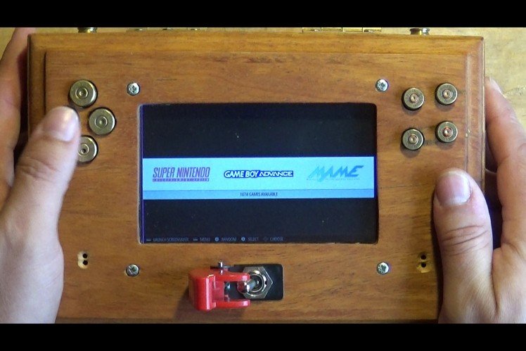
Wooden Pi Handheld Games Console With Bullet Buttons

Made by Dubious Engineering / Games & Gaming
About the project
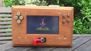
A guide to build your own handheld games console out of wood using bullet shells for buttons and a missile switch works with RetroPie and EmulationStation on the Raspberry Pi and includes a tiny audio amplifier, speakers and a LithiumIon iPad battery. Build Videos included to show how/how not - 10 mins of entertainment!
Project info
Items used in this project
Hardware components


Story
Quick video overview....
https://youtu.be/peaa1aaXyfU
Dubious Engineering on YouTube
Step 1: Tools, Ingredients and Planning Component Layout
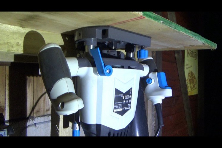
I installed a router in my folding workshop bench in my solar powered shed (shed video below), and started getting used to using the router, I have never used a router before, I know they are dangerous, but also very useful... So, learning by experience I had a play around - please be careful, this kind of gear can do serious damage!
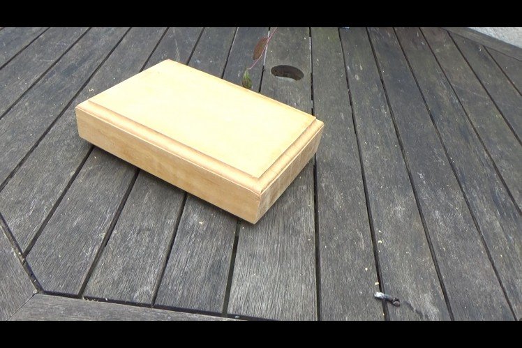
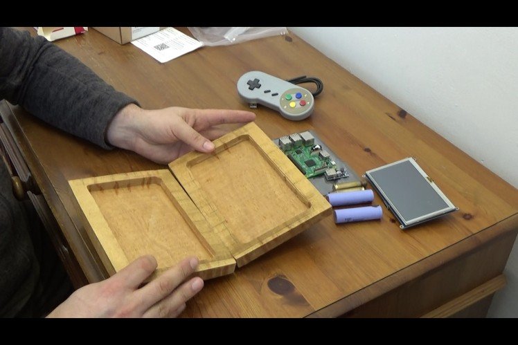
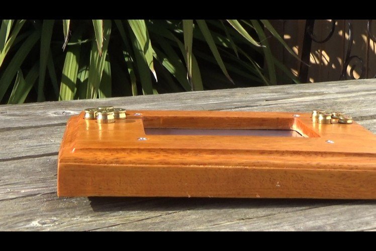
The wood was kindly given to me by a friend - its African hardwood. The first thing I did was bevel the edges of the wood and cut a space into the inside of the two halves of the wood to create an enclosure. All of this has been done by hand/by eye, so nothing is prefect, and it has that hand-made look and appeal.
I then started laying out components to see where they will fit. I will go-over the component list on the next page.
Tools - Hand Saw, Round Files, Sandpaper, Router, Drill, Drill bits, Screwdrivers, Soldering Iron, solder and some basic skills.
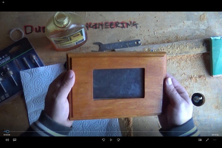
Step 2: Routing the Case and Oiling the Wood
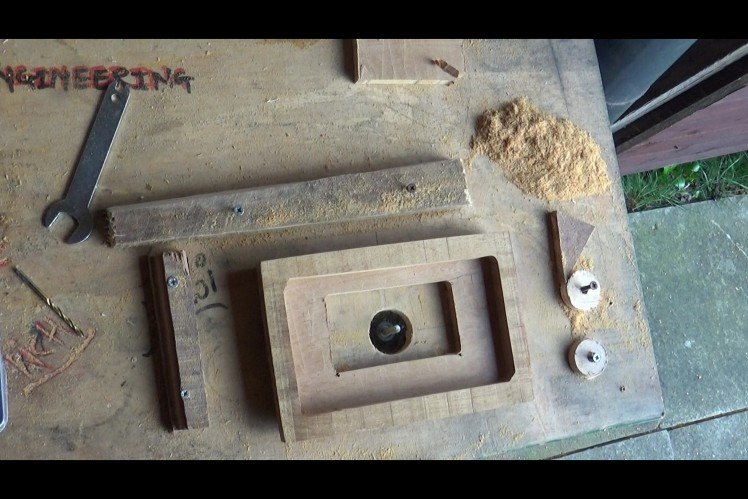
So, having learnt a few routing skills, like using guide fences and gates, I now start to mark-up where the components will fit and start to route appropriate sized apertures, placing components, marking them out in pencil and also trying to take into account where other components will fit in the future.
I would cut a little, check the fit and cut some more - I didn't want to cut too much and then end up with a problem!
Component list -
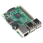
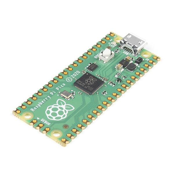
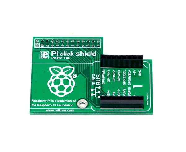
- RaspberryPi with RetroPie installed on SD card
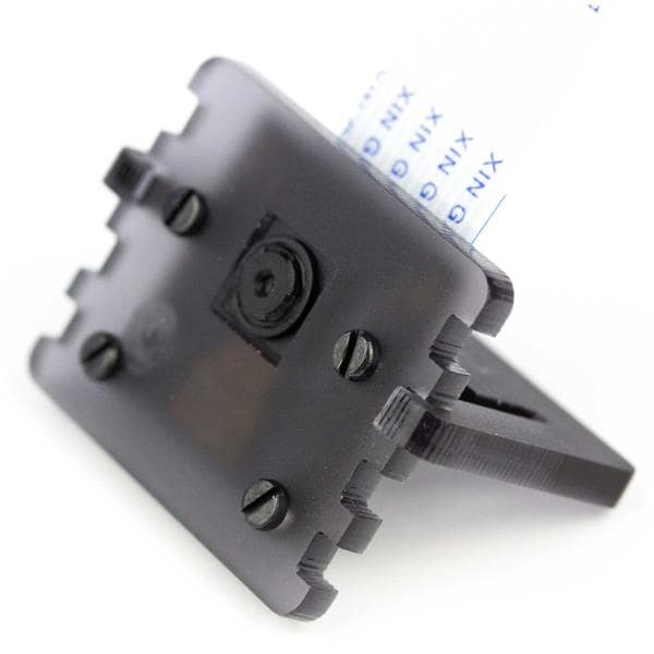
- Touch Screen to fit RaspberryPi
- Handheld Games Controller (PCB will be salvaged from this)
- Lithium Ion Batteries and miniature Battery Charge PCB
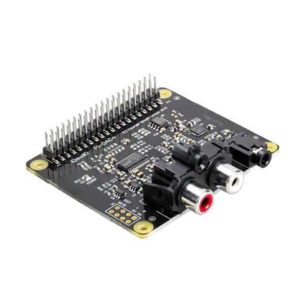
- Miniature stereo amplifier and speakers
- Bullet push buttons
- Various colours of small gauge hookup wire
Step 3: Testing the Parts
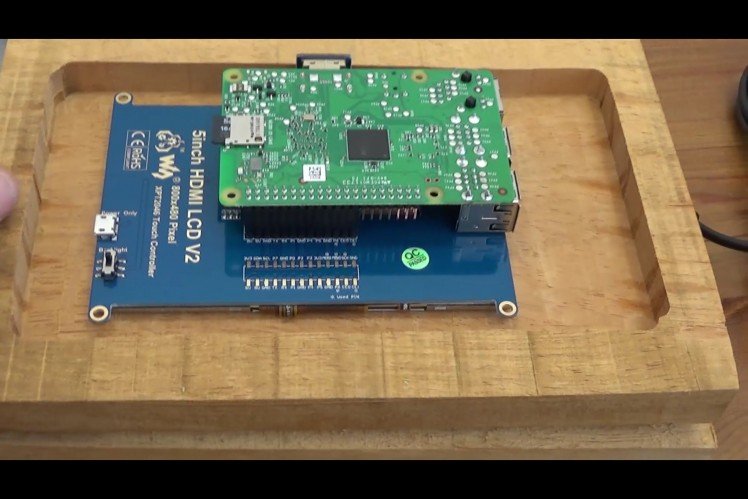
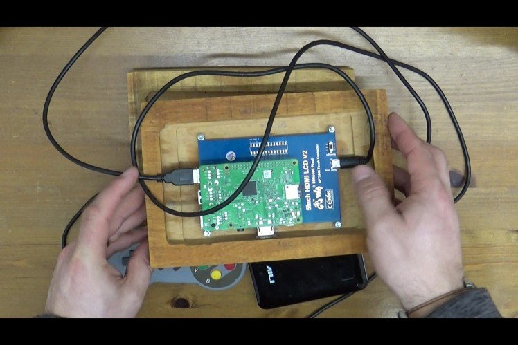
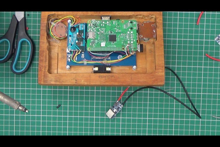
So, using a had-drill, I fitted the RaspberryPi and the screen to the routed wooden case. At this point, I thought it would be good to test most of the major components of the build to make sure it works. This also gave me the opportunity to take apart the game controller and understand a little more about how to make best use of the PCB.
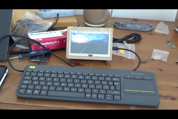
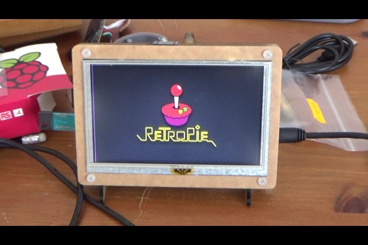
Step 4: Install and Test the Pi and Screen
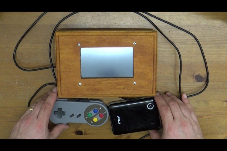
Testing the parts by using a 5v USB battery supply/wall charger early-on, make sure things are working to your satisfaction before cutting more holes and committing to specific hardware options as you may need to change your design if some items are not compatible.
This is a great opportunity to check the fit form and function of your hardware!
Step 5: Make Bullet Case Buttons
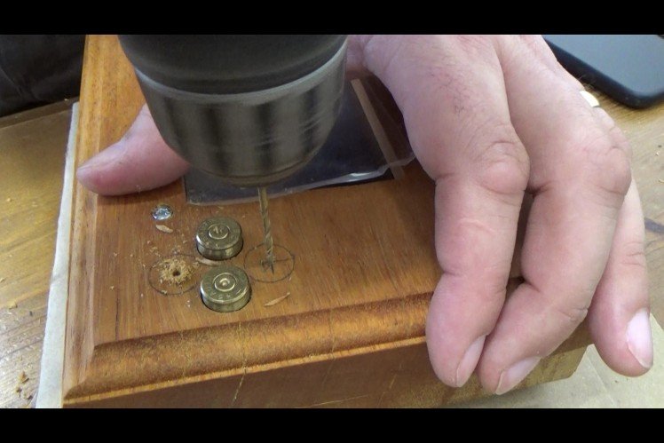
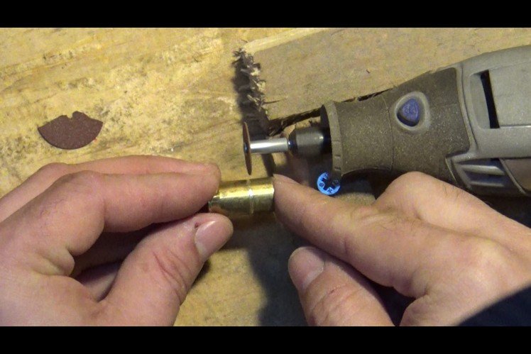
I was kindly donated some brass bullet casings by a friend, and have tried a couple of different methods of integrating them into my build. The first method, shown below didnt work out so well, the buttons came un-glues, the rubber pads didn't work very well... so... in future videos, you will see I employ microswitches! - WAY WAY BETTER...
Also, go slow and easy with your drill... I split the case here using my electric drill, and nearly cried!! It was a very frustrating moment!
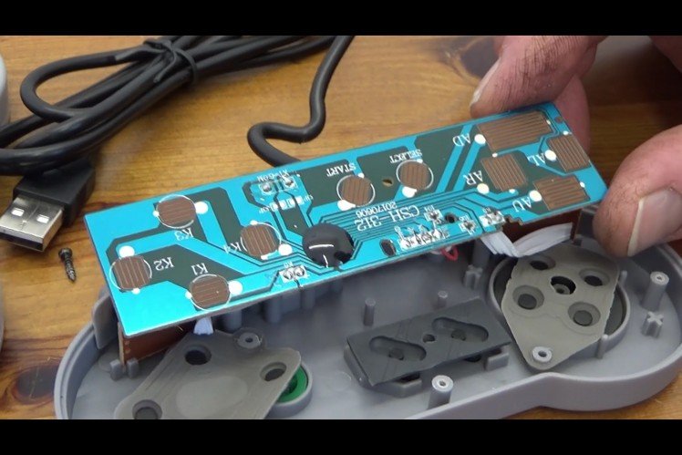
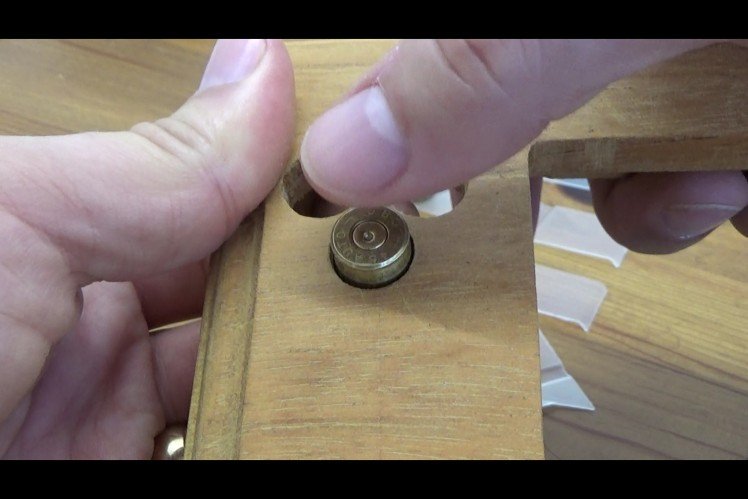
Step 6: Install the Controller PCB Assembly and Test!
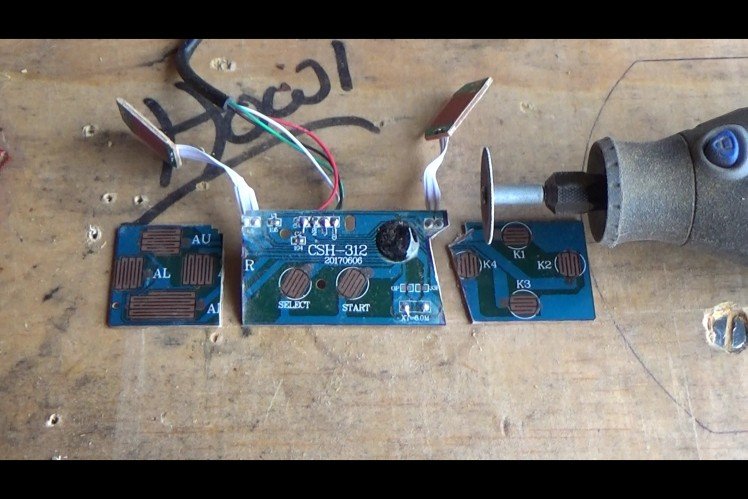
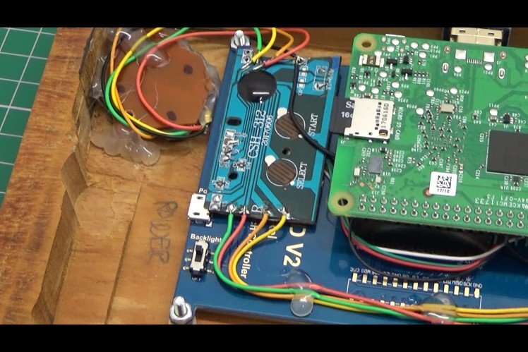
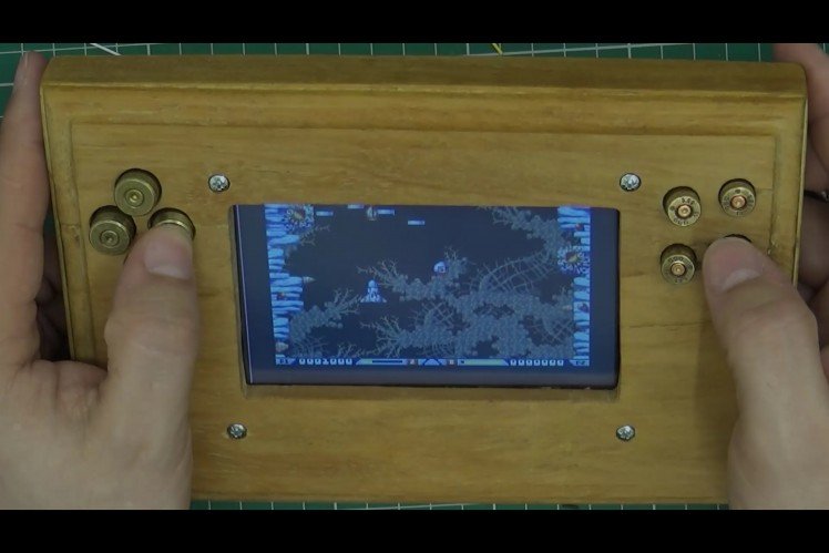
The bullet buttons used in conjunction with the rubber pads on the had-controller didn't work very well, but gave me the opportunity to prove concept and test the unit! - It also allowed me to plan where I will fit the controller PCB and associated wiring. In future videos you will see I use microswitches instead of the rubber pads which gives a much more positive feedback to the user.
Step 7: Install the Power Supply and Connect the Two Halves Together
Now to make the unit battery powered...
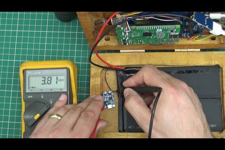
I used an iPad battery, a small battery charger PCB and a 2amp 5v boost-converter PCB to power the Pi and Screen. With this combination, you can achieve about 4 hours of gaming time.
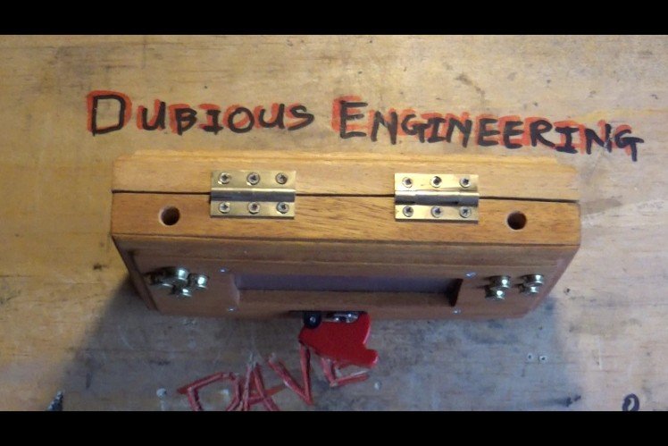
The battery is in the lower half of the clam-shell, the pi, screen and electronics are in the upper half of the clam-shell. I have hinged the clam-shell together.
Step 8: Install an Audio System and Test!
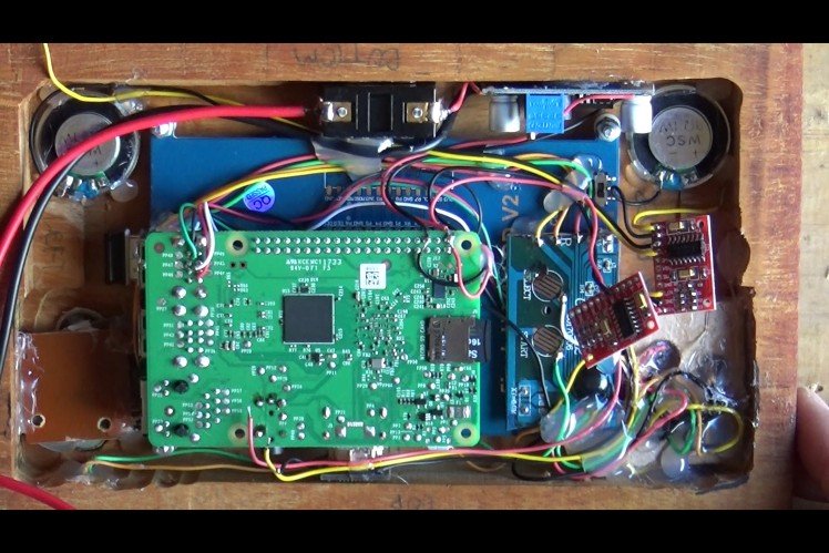
My next mission was to find an audio system that was small enough to fit into this unit. A short search on ebay revealed a 5v audio amplifier for £1 and also some small, thin speakers popped up for around £2.... all good budget stuff!
Just for effect and in keeping with the army-theme to this unit, I fitted a missile switch as a power switch.
So, it's about finished, I do plan a few minor modifications, but for all intents and purposes, this works a treat now!
I put all of this up so that if you decide to make something similar you can learn from me and not make the same mistakes I made along the way!!
I hope this has been entertaining and useful!
Howard - "Dubious Engineering" on YouTube
Schematics, diagrams and documents
Credits
Dubious Engineering
Creator, Engineer, YouTuber - Continue to come to ElectroMaker also, visit and subscribe to Dubious Engineering on YouTube for regular updates and product reviews!
Related products


Leave your feedback...