





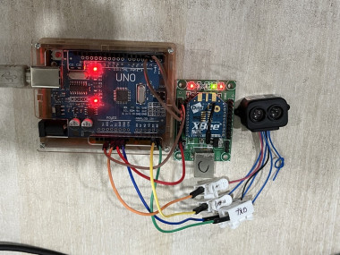
Wireless Distance Monitoring With Tf-luna Lidar And Xbee

Made by chanchaldada / IoT
About the project
A client came to us with a straightforward-sounding request: they needed to monitor the distance between a moving gantry crane and a storage rack in real time.
Project info
Items used in this project
Hardware components



Story
How our embedded team built a long-range wireless distance monitoring system for a client's industrial safety application — and why it turned out to be a perfect example of why you should hire dedicated Arduino freelancers instead of rolling your own solution.
The Problem: Wired LiDAR Just Wasn't Going to Cut It
If the gap closed below a safety threshold, the system had to trigger an alarm. Sounds simple enough — until you factor in that the crane travels 40 meters across the factory floor, and running a cable along that path was a non-starter.
The existing solution used a wired ultrasonic sensor, but it kept getting false triggers from ambient noise and had a range of only about 4 meters. They wanted something with better accuracy, longer range, and no physical connection between the sensor node and the monitoring station.
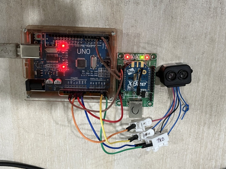
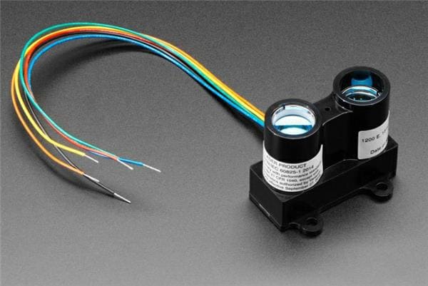
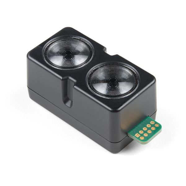
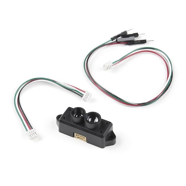
We proposed a wireless LiDAR-based system using the TF-Luna module paired with an Arduino Uno and XBee radios. Here's how we built it.
Architecture Overview
The system splits into two halves:
Sensor Node (on the crane):
- TF-Luna LiDAR → Arduino Uno (UART RX/TX)
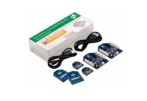
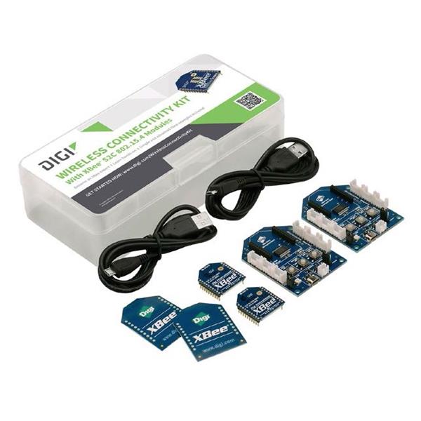
- Arduino Uno → XBee S2C (Serial TX/RX)
- Power: 12V DC → LM2596 → 5V rail
Monitoring Station (fixed location):
- XBee S2C → Arduino Uno (Serial RX)
- Arduino Uno → Buzzer + LCD
The XBee modules run in AT mode (transparent serial), which means the Arduino code treats them as a dumb serial pipe. No packet framing, no ZigBee stack handling — just `Serial.write()` on one end and `Serial.read()` on the other. For a simple point-to-point link, this keeps the firmware dead simple.
The Firmware: No RTOS, No BS
We wrote the firmware in plain Arduino C++ — no Zephyr RTOS, no FreeRTOS. For a single-sensor, single-receiver topology, an RTOS is overkill. The loop is simple:
```cpp
// Sensor node side
void loop() {
uint8_t buf[9];
if (readTFLunaFrame(buf)) {
int distance = parseDistance(buf);
Serial.println(distance); // to XBee
}
delay(50); // 20Hz update rate
}
```
The TF-Luna outputs a 9-byte frame over UART at 115200 baud by default. The frame contains distance (in cm), signal strength, and temperature. We parse only the distance bytes (bytes 0–1, little-endian) and push the value out over serial.
Key detail: We set the TF-Luna to 100Hz internal measurement mode but only polled at 20Hz. This gave us time-averaged readings that were more stable than raw 10ms samples, which bounced around ±3cm due to the target's surface reflectivity.
On the receiver side, we used a simple state machine to parse the incoming ASCII distance values, then compared against a configurable threshold (set via a potentiometer on an analog pin — no need for menus or EEPROM in a prototype).
The Wireless Link: XBee Configuration Pitfalls
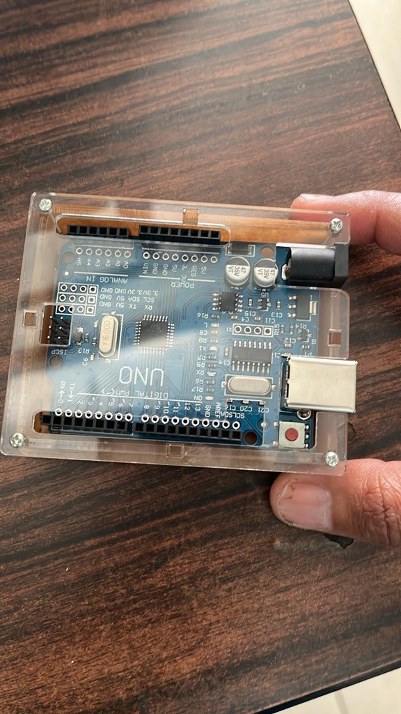
Here's where things got interesting. The XBee S2C modules default to AT mode with a baud rate of 9600. The TF-Luna wants 115200. If you're not careful, you'll mix up the two serial baud rates and wonder why you're getting garbage.
We used SoftwareSerial on pins 2 and 3 for the TF-Luna, leaving the hardware UART (pins 0/1) dedicated to the XBee. This is a crucial detail — if you try to run both on hardware serial, you'll run into conflicts with the USB programming interface.
To configure the XBee modules, we used the Digi XBee Configuration Tool (free, runs on Windows/macOS/Linux). Both modules were set to:
- Baud: 9600 (to match Arduino's hardware serial)
- Destination Address High/Low: 0x00000000 / 0xFFFF (broadcast, for simplicity)
- PAN ID: 0x1234 (custom, to avoid interference with other ZigBee networks in the building)
Range test: In the factory environment, we measured a solid link at 65 meters line-of-sight with 0% packet loss. That's well beyond the 40 meters needed, so we had headroom.
One thing we learned the hard way: the XBee S2C's default transmit power is +8dBm. If you need more range, you can bump it to +18dBm via the `ATPL` command, but this increases current draw from ~40mA to ~250mA. For battery-powered nodes, that's a real consideration. Our client had mains power available on the crane, so we went with maximum power.
Power Supply Design: The Part Everyone Underestimates
The TF-Luna is sensitive to voltage ripple. The datasheet calls for 5V ±0.1V, and in practice, we saw erratic readings when the supply dipped below 4.8V.
The crane's electrical system had significant noise — motor starts caused transient drops of up to 1.5V on the 12V rail. We solved this with:
1. LM2596 buck converter set to 5.2V (slightly above nominal, to account for line losses)
2. 1000µF electrolytic capacitor across the 5V rail
3. 0.1µF ceramic capacitor right at the TF-Luna's VCC pin
This combo kept the LiDAR happy even during crane motor inrush. If you're planning something similar, don't skip the bulk capacitance — we did in the first prototype and got readings that jumped around by ±20cm whenever the crane moved.
Why This Was a Job for Dedicated Arduino Freelancers
Here's the thing: the client's in-house team was three full-time mechanical engineers. They could design the mounting bracket, but firmware, wireless configuration, and PCB layout were outside their wheelhouse.
They initially tried to hack it together with an off-the-shelf Bluetooth module and a phone app. It worked in the office, but in the factory, the Bluetooth link dropped every time a forklift drove between the sensor and the receiver. That's when they called us.
The timeline:
| Phase | Duration | Deliverable |
|-------|----------|-------------|
| Requirements + architecture | 2 days | System design doc, component selection |
| Firmware + hardware prototype | 5 days | Bench-tested sensor node + receiver |
| Wireless range testing | 3 days | Range report, threshold calibration |
| Enclosure + field installation | 4 days | Fully assembled, mounted, and verified |
| Documentation + handover | 2 days | Schematic, source code, user guide |
Total: 16 working days from kickoff to working system. The client's estimate for doing it in-house was 6–8 weeks, assuming they could learn the wireless stack, debug the LiDAR interface, and deal with the power issues — none of which they'd done before.
The math is pretty clear: hiring us cost less than the opportunity cost of a month of their engineers' time diverted from their core product work.
Lessons Learned (The Honest Version)
1. The TF-Luna's stated 8m range is optimistic. We got reliable readings up to 6.5m on a matte black surface. On a white reflective surface, we hit the full 8m. Know your target material before you spec the sensor.
2. XBee AT mode is fine for point-to-point, but don't build a mesh with it. If you need multiple sensor nodes talking to one receiver, switch to API mode and handle addressing in firmware. We kept it simple because the use case was one-to-one.
3. The Arduino Uno's 16MHz clock and 2KB SRAM are plenty for this. We used about 40% of flash and 55% of RAM. If you're doing something more complex — say, logging data to an SD card while streaming over wireless — you'll hit the Uno's limits fast. That's when you step up to an STM32 or ESP32.
4. Always add a watchdog timer. Our first field test had the Arduino hang after a brownout on the crane's power line. A simple `wdt_enable(WDTO_2S)` in `setup()` and a `wdt_reset()` in the main loop saved us from a remote-site visit.
Final Thoughts
This project is a textbook example of when to bring in specialized help. The components are cheap, the code is short, but the integration details — power integrity, wireless configuration, environmental factors — are where projects die.
If you're staring at a similar problem and thinking "I could probably figure this out," you're right. You probably could. The question is whether your time is better spent doing that, or focusing on your actual product. For our client, the answer was clear.
If you need a similar system built — or if you're already in the weeds and need someone to pull you out — our team is available for freelance embedded development engagements. We've shipped over 40 prototype systems across industrial, agricultural, and consumer applications. We work remotely, ship prototypes worldwide, and we don't pad timelines.
— The DigitalMonk Engineering Team
Credits
chanchaldada
Chanchal Dada is an IoT developer at DigitalMonk, focused on building smart embedded systems using Arduino and ESP32. She specializes in IoT-based automation, smart monitoring solutions, and real-world hardware-software integration for practical applications.
Related products








Leave your feedback...