
Wireless Audio Transmission Using Li-fi

Made by yeshvanth-m
About the project
Wireless Audio Transmission using Li-Fi using Red Pitaya
Project info
Difficulty: Moderate
Platforms: Digilent, Red Pitaya
Estimated time: 6 hours
License: GNU General Public License, version 3 or later (GPL3+)
Items used in this project
Hardware components

View all
Story
Li-Fi (also written as LiFi) acronym for Light Fidelity is a wireless communication technology that utilizes light to transmit data and position between devices. It is capable of transmitting data at high speeds over visible light, ultraviolet, and infrared spectrums. In its present state, only LED lamps can be used for the transmission of data in visible light. In terms of its end-use, the technology is similar to Wi-Fi — the key technical difference being that Wi-Fi uses radio frequency to induce a voltage in an antenna to transmit data, whereas Li-Fi uses the modulation of light intensity to transmit data. Li-Fi can theoretically transmit at speeds of up to 100 Gbit/s. Li-Fi's ability to safely function in areas otherwise susceptible to electromagnetic interference (e.g. aircraft cabins, hospitals, military) is an advantage. The technology is being developed by several organizations across the globe.
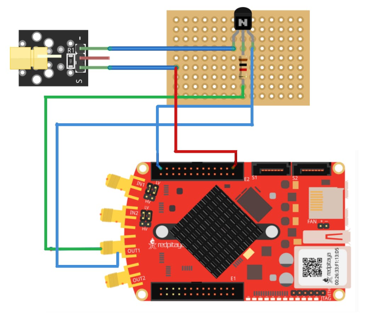
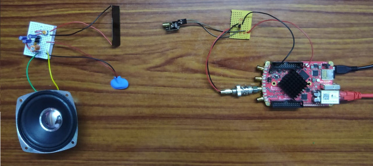
Li-Fi ModulatorThe Red Pitaya has 2 Fast Analog RF Outputs as shown below in the block diagram:

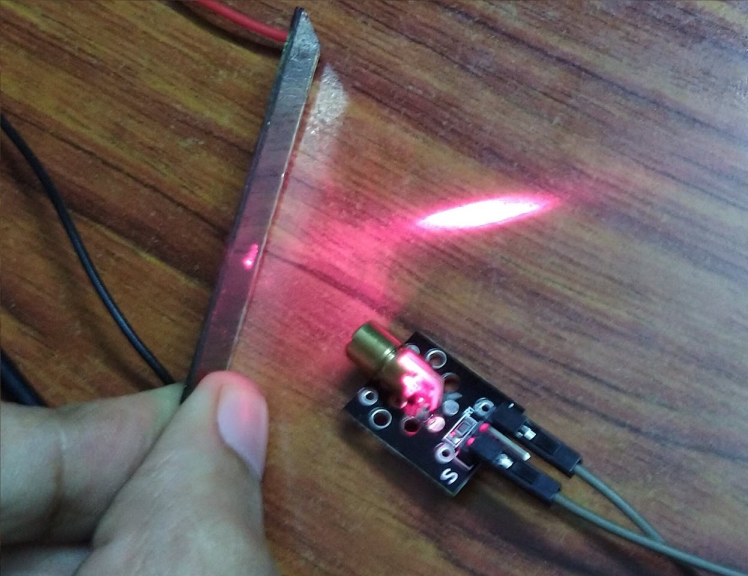
- The laser diode can transmit light pulses only in digital form, that is 1s and 0s, it's a 1 if the laser diode is ON and it's a 0 if the laser diode is OFF.
- The specification of the RF Outputs are ± 1V Max. amplitude and DC-40MHz.
- Thus, to power the Laser Module, a transistor is used as a switch.
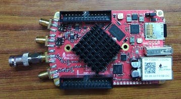
- Red Pitaya STEMlab 125-10 Starter Kit
- Perf Board and Soldering Kit
- BNC Connector
- SMA to BNC Converter
- Laser Diode Module
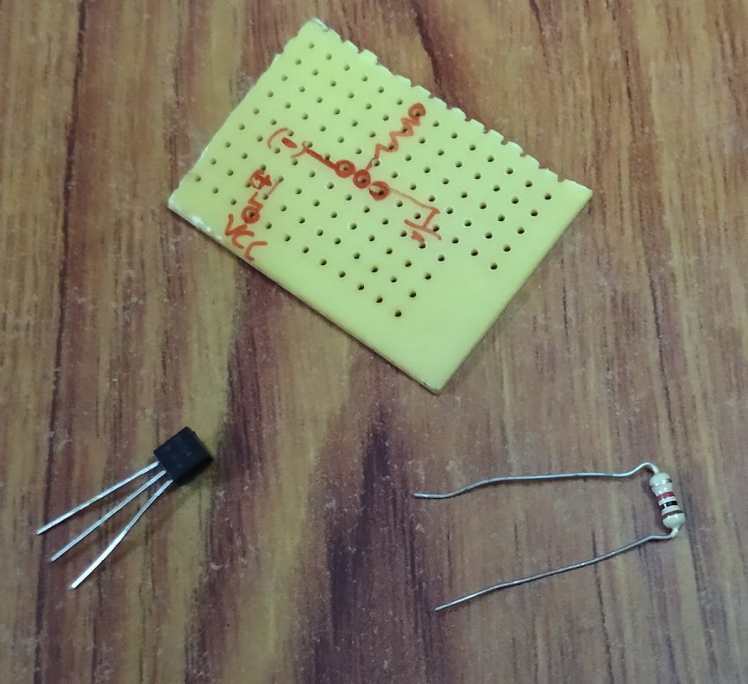
- NPN Transistor (BC547)
- Resistor (1k)
- Wires and Jumpers
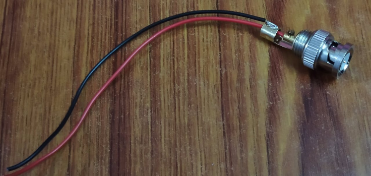
- Take a BNC connector and connect wires to its terminals
- Take a perf board and solder the components including the BNC with wires to it according to the circuit diagram
- Connect the SMA to BNC converter to Red Pitaya
- Finally connect the BNC of the modulator to Red Pitaya
Choosing the right solar cell
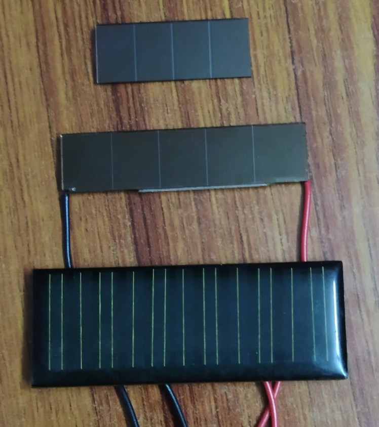
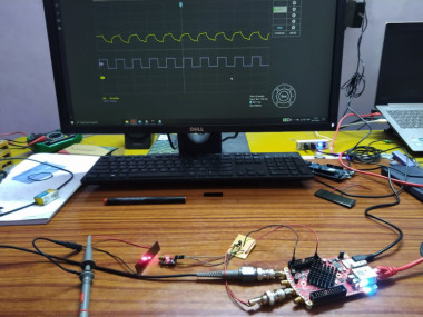
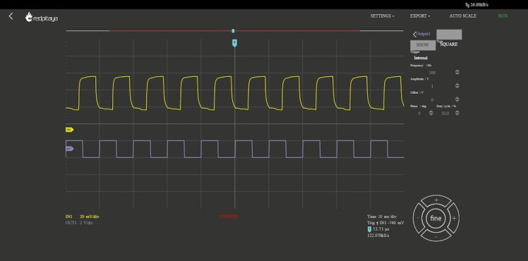
Different solar cells give different output powers, and so does the amount of noise in the output of the demodulator. Connect the solar cell that is to be analyzed to the input probe and open the oscilloscope and function generator app and analyze the output waveform to different frequencies

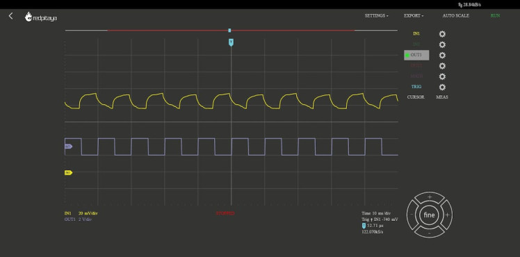
Same way analyze the output for different solar cells
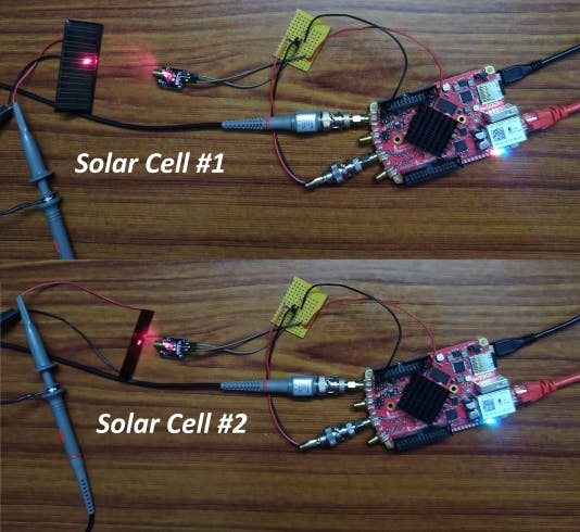
Solar Cell #1 Response
Solar Cell #2 Response
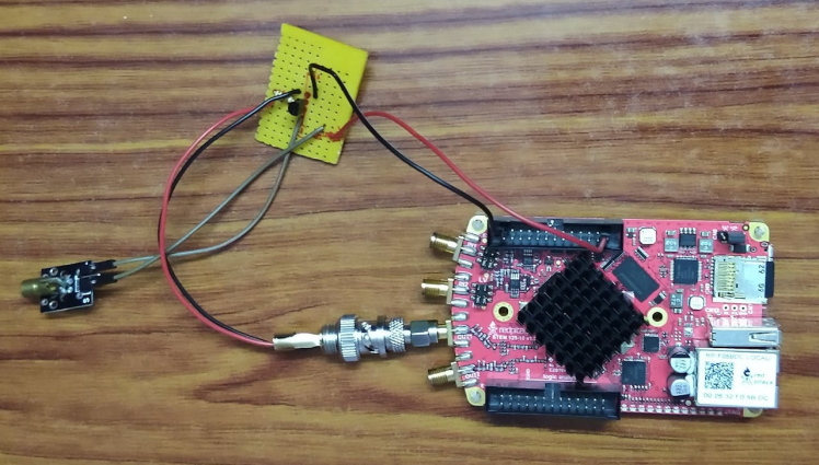
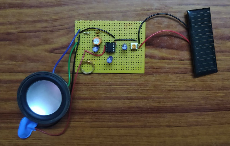
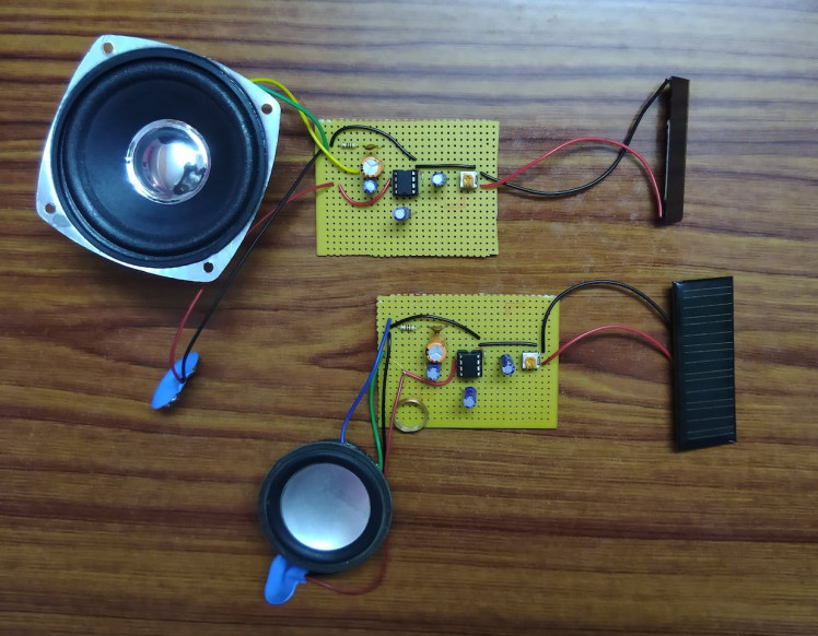
The Li-Fi demodulator is a standalone device with Audio Amplifier and a solar cell to demodulate the received light signals. A potentiometer is required to adjust the level of the input signal depending on the solar cell and environment. This is also to reduce the noise level. The solar cell receiver converts the received light signals into corresponding voltage levels which are fed into the amplifier which provides the required gain and then the amplified signal is fed into the speaker, when the frequency is in the audible range to human ears - about 20 Hz to 20 kHz we will be able to hear the sound.
Circuit Diagram of Li-Fi Demodulator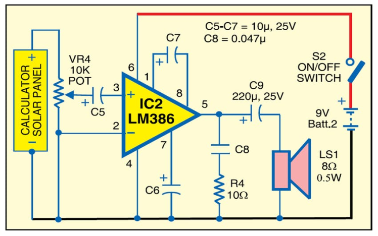
- Perf Board and Soldering Kit / Bread Board
- LM386 Audio Amplifier IC
- Solar Cell
- 10k Potentiometer (Preset)
- Capacitors - 1 × 0.047uF, 3 × 10uF, 1 × 220uF
- Resistor - 10 Ohms
- Speaker 8 Ohms, 0.5W
- 9V Battery and Cap
- Wires and Jumpers
- 4 Ohms Coil if using 4 Ohms Speaker
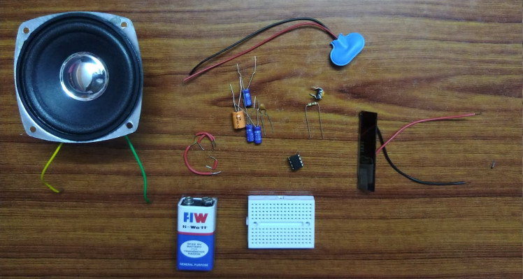
Gather the components and prototype using the breadboard
Assembled Prototype

Test Setup
The above video shows the frequency response of the Li-Fi system. The next stage is building the Li-Fi Receiver
Building the Li-Fi DemodulatorAssemble the circuit in a perf board and finish the soldering.
Red Pitaya board can be controlled remotely over LAN or wireless interface using MATLAB, LabVIEW, Scilab, or Python via Red Pitaya SCPI (Standard Commands for Programmable Instrumentation) list of commands. SCPI interface/environment is commonly used to control T&M instruments for development, research, or test automation purposes. SCPI uses a set of SCPI commands that are recognized by the instruments to enable specific actions to be taken (e.g.: acquiring data from fast analog inputs, generating signals, and controlling other peripheries of the Red Pitaya platform). The SCPI commands are extremely useful when a complex signal analysis is required where SW environment such as MATLAB provides powerful data analysis tools and SCPI commands simple access to raw data acquired on the Red Pitaya board.
Features
- Quickly write control routines and programs using MATLAB, LabVIEW, Scilab, or Python
- Write testing scripts and routines
- Take quick measurements directly with your PC
Block Diagram explaining SCPI on Red Pitaya
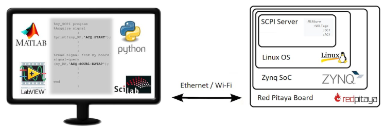
The Red Pitaya Module in Python provides methods that are easy to implement. Refer to the documentation for more information on SCPI.
The following SCPI command is used to set the frequency of the fast analog output channel in Python:
rp_s.tx_txt('SOUR1:FREQ:FIX ' + str(f))Where f is desired frequency to be outputted.
To know more about interfacing Red Pitaya with Python, watch the following video:
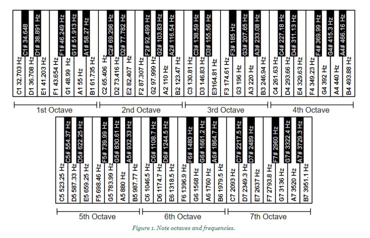
Playing tonesTo play the keyboard notes, we need to know the frequency of each note. For simplicity reasons, I took the 5th octave.
Here's an image from Digilent's Reference:
The respective frequencies of the keyboard notes for a song with the required delay are to be sent to the SCPI server. Refer to the code in the Python directory of this repository.
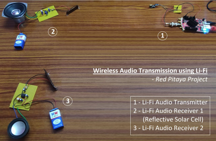
Testing the Li-Fi Audio SystemLi-Fi Audio System with Multiple ReceiversReflective Solar Cell
To have multiple receivers to the same light signal, a reflective solar cell is required as shown in the image below.
This specific type of Solar Cell absorbs some light falling on it and reflects the rest.
Block Diagram of the Multiple Receiver Setup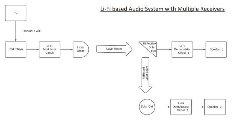
When light is reflected from a surface, the angle of incidence is always equal to the angle of reflection, where both angles are measured from the path of the light to the normal to the surface at the point at which light strikes the surface. This is called the law of reflection. Thus, multiple receivers can be used by proper placement of Solar Cells.
Two sets of receivers are to be built for this model
- Python version 3.10.0 or above
- Once you're done with the hardware, make sure you give the right connections as mentioned in the circuit diagrams.
- Go to the Red Pitaya's Home Page > Development > Run
- Note down the IP address in which the SCPI server is hosted.
- Create a directory in your local machine and clone this repository using the command
$ git clone https://github.com/yeshvanth-m/Wireless-Audio-Transmission-using-Li-Fi.git- Navigate to the Python Folder and then run the following command, say the IP address of the SCPI server is "192.168.137.43"
$ python Play_Music.py 192.168.137.43The Play_Music.py file contains the code for generating the Piano Music. I've set the frequencies corresponding to the 5th Octave, however, you may modify the code and add additional functionalities.
The string notes contain the keyboard notes and the delays for a particular song. You can play any music of your choice just by editing the notes string. For example, the Piano Notes for “London Bridge is falling down” is given as
notes = "g a g f e f g , d e f , e f g , g a g f e f g . d , g . e c"And, the notes for "Mary Had a Little Lamb" is give as
notes = "e d c d e e e , d d d , e e e , e d c d e e e e d d e d c"You can write notes for any other piano song the same way.
AcknowledgementsI would like to thank the Red Pitaya team for sending me the STEMlab 125-10 Starter Kit and giving me this opportunity to explore and learn new things!
Leave your feedback...