
Ultrasonic module test with stone lcd Module

Made by Zazenergyli
About the project
Ultrasonic module test with STONE lcd Module
Project info
Difficulty: Easy
Platforms: Arduino, circuito.io, STM32 Nucleo, TinyCircuits
Estimated time: 1 hour
License: GNU General Public License, version 3 or later (GPL3+)
Items used in this project
Hardware components

Story
The principle of ultrasonic distance measurement
The ultrasonic wave has strong directivity and the distance spread in the medium is far. Therefore, the ultrasonic wave is often used for distance measurements, such as distance measuring instrument and object-level measuring instrument, which can be realized through the ultrasonic waves. Ultrasonic testing is often more rapid, convenient, simple calculation, easy to achieve real-time control, and in terms of measuring accuracy can meet the requirements of industrial practical, so in the development of mobile robot has been widely used.
The principle of ultrasonic ranging is that the ultrasonic wave is emitted by the ultrasonic transmitter, which is based on the time difference when the receiver receives the ultrasonic wave, similar to the principle of radar ranging. The ultrasonic transmitter sends an ultrasonic wave to a certain direction, begin timing at the same time when launching, ultrasonic wave spreads in the air, encounter obstacle on the way to return immediately, ultrasonic receiver receives reflected wave to stop timing immediately.
(the propagation speed of the ultrasonic wave in the air is 340m/s. According to the time t (seconds) recorded by the timer, the distance (s) from the launching point to the obstacle can be calculated, that is s=340t/2).
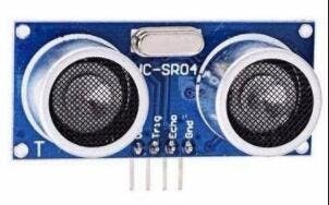
Hc-sr04 is an ultrasonic transmitter and receiver module that electronics enthusiasts often use for their own experiments.
This module has stable performance, accurate measurement distance, high precision, and small blind area.
Main technical parameters:
· Operating voltage: DC-- -5v
· Static current: less than 2mA
· Level output: high 5V
· Level output: bottom 0V
· Induction Angle: no more than 15 degrees
· Detection range: 2cm-450cm
· High precision: up to 0.2cm
HC-SR04 Module schematic
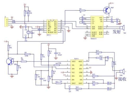
This picture is the schematic diagram of the hc-sr04 ultrasonic module. If you are interested in the principle of hardware, you can look it up on the Internet.
Wiring: VCC, trig (control terminal), echo (receiver terminal), GND Basic working principle:
① IO port TRIG is used to trigger the ranging and give a high-level signal of at least 10us;
② the module automatically sends 8 square waves of 40khz to automatically detect whether there is a signal return;
③ a signal is returned and a high level is an output through the IO port ECHO. The duration of the high level is the time from the transmission to the return of the ultrasonic wave.Test distance =(high level time * sound velocity (340M/S))/2;
This module USES method is simple, the mouth sends a high level of more than ten us, you can receive the mouth for high-level output. To be able to open timer timing, an output when the mouth into low electricity at ordinary times the value of the timer can be read, this is for the distance of time can calculate the distance. So constantly cycle test, which can reach your measuring values.
· Robot obstacle avoidance
· The object distance
· Liquid level detection
· The public security
· Parking lot survey
STM32F103RCT6 is very powerful, the following is the basic parameters of this MCU:
Series: STM32F10X
Kernel: ARM - COTEX32
Speed: 72 MHZ
Communication interface: CAN, I2C, IrDA, LIN, SPI, UART/USART, USB
Peripheral equipment: DMA, motor control PWM, PDR, POR, PVD, PWM, temperature sensor, WDT
Program storage capacity: 256KB
Program memory type: FLASH
RAM capacity: 48K
Voltage - power supply (Vcc/Vdd) : 2 V ~ 3.6 V
Oscillator: internal
Operating temperature: -40°C ~ 85°C
Package/enclosure: 64-lqfp
In this project, I will use UART, GPIO, Watch Dog, Timer of STM32F103RCT6.
The following is the code development record for this project.
STM32 USES Keil MDK software development, about this software you must be familiar, so I will not introduce the installation method of this software.
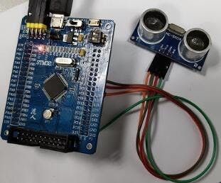
STM32 can be simulated and debugged online through j-link or st-link and other simulation tools. The following picture is the development board of STM32 I use:

The trig and echo ports are configured to low-level output, the output of more than 10 us trig pin high-level pulse (module automatically send out eight 40 k square wave), then wait, capture the output echo rise along, capture the rising edge at the same time, start the timer start timing, wait again to catch the falling edge of the echo, when capturing the falling edge, read the timer time, this is the running time of ultrasound in the air, in accordance with the S = (high level of time * (340 m/S)) / 2 can compute the distance of ultrasonic to the obstacles.
With this in mind, we can write a simple test code.
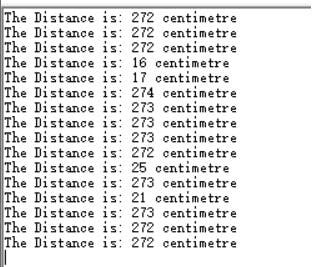
We can see the measurement results returned by the serial port.
The LCD module is STONE STVC050WT-01, which is very convenient to use. Previously, we used a serial port to display the distance measured by ultrasonic waves, while the LCD module of STONE also receives data and displays it to the module through UART. This process only needs to do a simple protocol encapsulation in the MCU.

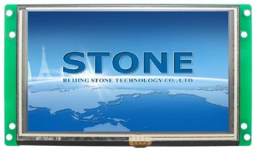
STVC050WT-01 is a TFT display and touch controller.It includes a processor, control program, driver, flash memory, RS232/RS485/TTL port, touch screen, power supply, etc. It is a powerful display system
The operating system is simple and can be controlled by any single-chip microcomputer. STVC050WT-01 can be used to perform all basic functions, such as text display, image display, curve display, touch function, video and audio function, etc.The user interface can be much richer and more diverse.Flash memory can store your data, configuration files, pictures, etc.
built-in Cortex CPU and driver
can be controlled by any single-chip microcomputer
show pictures/text/curves
65536 color TFT display
with/without the touch screen
RS232/ RS485/ TTL UART interface and USB port
wide voltage range
easy to use. Powerful features. Cost and time-saving.
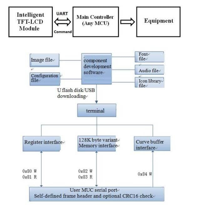
The intelligent TFT-LCD module communicates with the customer's MCU through commands (hexadecimal code), and the MCU then controls the connected device to work according to the commands received.
Use STONE's TFT-LCD module in only 3 steps:
1. Design a beautiful set of graphical user interfaces.
2. Connect directly to the customer's MCU through RS232, RS485, or TTL.Plug and play.
3. Write a simple program to control the TFT-LCD module by MCU command.(hexadecimal code).
TFT LCD module serial command frame consists of 5 data blocks, all serial command or data are expressed in hexadecimal format.The data transfer
In the MSB way.For example, for 0x1234, first send 0x12, then 0x34.
Common application scenarios are described in STONE's official website:

1 / 2


Construction machinery and vehicle equipment
About the use of STONE TOOL softwareAt present, the latest version of STONE TOOL software provided by STONE is TOOL2019. Open the software to create a new project, then import the previously designed UI display pictures, and then add your own buttons, text display boxes, etc. STONE's official website has a very complete tutorial on the use of this software. Interested friends can click on the following link:
https://www.stoneitech.com/support/download/video
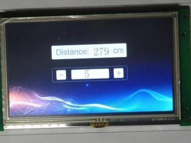
UI graphic design of STONE LCD moduleYou can use Photoshop or other image design software to set the UI interface. The interface I designed is as follows:
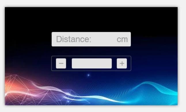
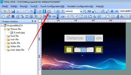
Click the button indicated by the arrow to generate the configuration file, and then download the configuration file into the display module to display the UI interface we designed.
This part of the content and tutorial I do not go into detail, you can go to theSTONE website to download a very detailed tutorial.
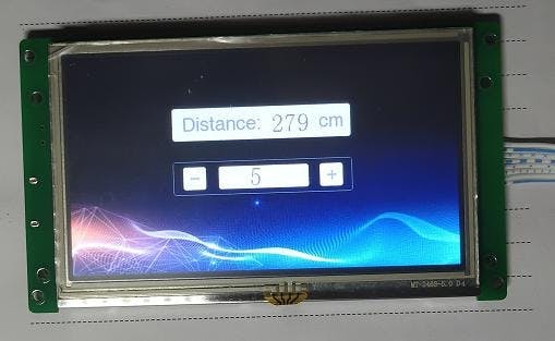
STM32 LCD Project implementation process with UART TTLThe functions of this demo are relatively simple, mainly including the following two points:
Display the distance measured by the ultrasonic module
Change the refresh time through the "+" and "-" buttons on the display
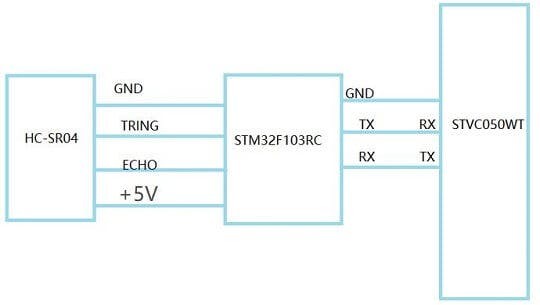
Reliability of STONE LCD project hardware connectionsHardware wiring is very simple, you can refer to the following picture of the connection:
STM32 microcontroller drive hc-sr04 program can be downloaded on the network, here I also use the user-provided demo routine to modify.
Peripheral resource usageMCU peripherals only use two GPIO pins (trig, echo) and a Timer.In addition, a UART is required to communicate with the STONE displayer.
Trig and echo ports are configured to low-level output, first of all to trig output at least 10 us high-level pulse (module automatically send out eight 40 k square wave), then wait, capture the output echo rise along, capture the rising edge at the same time, open the timer and start timing, wait again to catch the falling edge of the echo, when capturing the falling edge, read the timer time, this is the running time of ultrasound in the air, in accordance with the S = (high level of time * (340 m/S)) / 2 can compute the distance of ultrasonic to the obstacles.
Hc-sr04 algorithm source codevoid EXTI9_5_IRQHandler(void)
{
static u8 flag_Sta = 0;
if(EXTI_GetITStatus(EXTI_Line5) != RESET)
{
EXTI_ClearITPendingBit(EXTI_Line5);
if(GPIO_ReadInputDataBit(GPIOC,GPIO_Pin_5)==1)
{
TIM_SetCounter(TIM6,0);
flag_Sta=1;
TIM_Cmd(TIM6, ENABLE);
}
else
{
TIM_Cmd(TIM6, DISABLE);
if(flag_Sta)
{
Distance = TIM_GetCounter(TIM6);
Distance = Distance /29;
if(Distance > 300)
Distance = 300;
Done = 1;
}
flag_Sta=0;
}
}
}This is an external interrupted Handler of GPIO. Finally, the Distance measured by the ultrasonic module can be obtained by obtaining the value of the variable “distance”.
Main.c#include "usart1.h"
#include "Sonic.h"
#include "SysTick.h"
#define DISPLYER_ADDR 0x05
#define CHANGE_TIME_ADDR 0x10
u8 data_send[8]= {0xA5, 0x5A, 0x05, 0x82, 0x00, 0x00, 0x00,0x00};
extern u16 Distance;
extern u8 USART_RX_BUF[10];
extern u8 USART_RX_END;
extern u16 USART_RX_STA;
void UART1_Send_Array(u8 send_array[],unsigned char num)
{
u8 i=0;
while(i
{
USART_SendData(USART1,send_array[i]);
while( USART_GetFlagStatus(USART1,USART_FLAG_TC)!= SET);
i++;
}
}
/*
* Function£ºmain
*/
int main(void)
{
u8 time=0,time_set=100;
SysTick_Init();
USART1_Config(115200); /* USART1 INIT*/
TIM6_Init(); //TIM6 Init
Sonic_Init(); //Sonic_Init
// printf("STM32F103VET6_Sonic Test!rn");
// printf("2017-04-14 9:00rnrn");
while(1)
{
Delay_ms(10);
time++;
if(time>=time_set)
{
time=0;
data_send[5]=DISPLYER_ADDR;
data_send[6] = Distance >> 8;//hight
data_send[7] = Distance & 0x00ff;//low
UART1_Send_Array(data_send,8);
// printf("The Distance is: %d centimetrern",Distance);
}
if(USART_RX_END)
{
// UART1_Send_Array(USART_RX_BUF,8);
switch (USART_RX_BUF[5])
{
case CHANGE_TIME_ADDR:
time_set=USART_RX_BUF[7]*10;
break;
default:
USART_RX_END=0;
USART_RX_STA=0;
break;
}
USART_RX_END=0;
USART_RX_STA=0;
}
}
}
/******************* (C) COPYRIGHT 2017 *****END OF FILE************/#include "Sonic.h"
/*******************************************************************************
* Sonic Init
*******************************************************************************/
u32 Distance = 0;
u8 Done;
u32 __IO time_1ms = 0;
void TIM6_Init(void)
{
TIM_TimeBaseInitTypeDef TIM_TimeBaseStructure;
//NVIC_InitTypeDef NVIC_InitStructure;
/* TIM6 clock enable */
RCC_APB1PeriphClockCmd(RCC_APB1Periph_TIM6, ENABLE);
/* Time base configuration */
TIM_TimeBaseStructure.TIM_Period = 0xFFFF;
TIM_TimeBaseStructure.TIM_Prescaler = 142; //144£¬500K
TIM_TimeBaseStructure.TIM_ClockDivision = TIM_CKD_DIV1;
TIM_TimeBaseStructure.TIM_CounterMode = TIM_CounterMode_Up;
TIM_TimeBaseInit(TIM6, &TIM_TimeBaseStructure);
TIM_ITConfig(TIM6, TIM_IT_Update, DISABLE);
TIM_Cmd(TIM6, DISABLE);
}
void Sonic_Init(void)
{
NVIC_InitTypeDef NVIC_InitStructure;
EXTI_InitTypeDef EXTI_InitStructure;
GPIO_InitTypeDef GPIO_InitStructure;
RCC_APB2PeriphClockCmd( RCC_APB2Periph_GPIOC| RCC_APB2Periph_AFIO,ENABLE);
GPIO_InitStructure.GPIO_Mode = GPIO_Mode_Out_PP;
GPIO_InitStructure.GPIO_Speed = GPIO_Speed_50MHz;
GPIO_InitStructure.GPIO_Pin = GPIO_Pin_4; //PC4 Trig
GPIO_Init(GPIOC,&GPIO_InitStructure);
GPIO_InitStructure.GPIO_Mode= GPIO_Mode_IPD;
GPIO_InitStructure.GPIO_Pin=GPIO_Pin_5; //PC5 Echo
GPIO_Init(GPIOC,&GPIO_InitStructure);
GPIO_WriteBit(GPIOC,GPIO_Pin_4,(BitAction)0); //trig
//EXTI_DeInit();
EXTI_ClearITPendingBit(EXTI_Line5);
GPIO_EXTILineConfig(GPIO_PortSourceGPIOC,GPIO_PinSource5);
EXTI_InitStructure.EXTI_Line= EXTI_Line5;
EXTI_InitStructure.EXTI_Mode= EXTI_Mode_Interrupt;
EXTI_InitStructure.EXTI_Trigger= EXTI_Trigger_Rising_Falling;
EXTI_InitStructure.EXTI_LineCmd=ENABLE;
EXTI_Init(&EXTI_InitStructure);
NVIC_PriorityGroupConfig(NVIC_PriorityGroup_2);
NVIC_InitStructure.NVIC_IRQChannel = EXTI9_5_IRQn;
NVIC_InitStructure.NVIC_IRQChannelPreemptionPriority= 0;
NVIC_InitStructure.NVIC_IRQChannelSubPriority= 0;
NVIC_InitStructure.NVIC_IRQChannelCmd=ENABLE;
NVIC_Init(&NVIC_InitStructure);
Distance = 0;
Done = 1;
}
void Sonic_Trig(void)
{
u16 i = 0;
if((Done == 1)&&(time_1ms > 100))
{
time_1ms = 0;
GPIO_WriteBit(GPIOC,GPIO_Pin_4,(BitAction)1);
for(i=0;i<0xf0;i++);
GPIO_WriteBit(GPIOC,GPIO_Pin_4,(BitAction)0);
Done = 0;
}
}
void EXTI9_5_IRQHandler(void)
{
static u8 flag_Sta = 0;
if(EXTI_GetITStatus(EXTI_Line5) != RESET)
{
EXTI_ClearITPendingBit(EXTI_Line5);
if(GPIO_ReadInputDataBit(GPIOC,GPIO_Pin_5)==1)
{
TIM_SetCounter(TIM6,0);
flag_Sta=1;
TIM_Cmd(TIM6, ENABLE);
}
else
{
TIM_Cmd(TIM6, DISABLE);
if(flag_Sta)
{
Distance = TIM_GetCounter(TIM6);
Distance = Distance /29;
if(Distance > 300)
Distance = 300;
Done = 1;
}
flag_Sta=0;
}
}
}
/******************* (C) COPYRIGHT 2017 *END OF FILE************/#include "usart1.h"
void USART1_Config(uint32_t uBaud)
{
USART1_Configuration(uBaud);
USART1_NVIC_Configuration();
}
void USART1_Configuration(uint32_t uBaud)
{
GPIO_InitTypeDef GPIO_InitStructure;
USART_InitTypeDef USART_InitStructure;
/* config USART1 clock */
RCC_APB2PeriphClockCmd(RCC_APB2Periph_USART1 | RCC_APB2Periph_GPIOA, ENABLE);
/* USART1 GPIO config */
/* Configure USART1 Tx (PA.09) as alternate function push-pull */
GPIO_InitStructure.GPIO_Pin = GPIO_Pin_9;
GPIO_InitStructure.GPIO_Mode = GPIO_Mode_AF_PP;
GPIO_InitStructure.GPIO_Speed = GPIO_Speed_50MHz;
GPIO_Init(GPIOA, &GPIO_InitStructure);
/* Configure USART1 Rx (PA.10) as input floating */
GPIO_InitStructure.GPIO_Pin = GPIO_Pin_10;
GPIO_InitStructure.GPIO_Mode = GPIO_Mode_IN_FLOATING;
GPIO_Init(GPIOA, &GPIO_InitStructure);
/* USART1 mode config */
USART_InitStructure.USART_BaudRate = uBaud;
USART_InitStructure.USART_WordLength = USART_WordLength_8b;
USART_InitStructure.USART_StopBits = USART_StopBits_1;
USART_InitStructure.USART_Parity = USART_Parity_No ;
USART_InitStructure.USART_HardwareFlowControl = USART_HardwareFlowControl_None;
USART_InitStructure.USART_Mode = USART_Mode_Rx | USART_Mode_Tx;
USART_Init(USART1, &USART_InitStructure);
USART_ITConfig(USART1, USART_IT_RXNE, ENABLE);
USART_Cmd(USART1, ENABLE);
}
void USART1_NVIC_Configuration(void)
{
NVIC_InitTypeDef NVIC_InitStructure;
/* Configure the NVIC Preemption Priority Bits */
NVIC_PriorityGroupConfig(NVIC_PriorityGroup_4);
/* Enable the USARTy Interrupt */
NVIC_InitStructure.NVIC_IRQChannel = USART1_IRQn;
NVIC_InitStructure.NVIC_IRQChannelPreemptionPriority = 2;
NVIC_InitStructure.NVIC_IRQChannelSubPriority = 0;
NVIC_InitStructure.NVIC_IRQChannelCmd = ENABLE;
NVIC_Init(&NVIC_InitStructure);
}
int fputc(int ch, FILE *f)
{
USART_SendData(USART1, (unsigned char) ch);
while (!(USART1->SR & USART_FLAG_TXE));
//while( USART_GetFlagStatus(USART1,USART_FLAG_TC)!= SET);
return (ch);
}
u16 USART_RX_STA=0;
u8 USART_RX_END=0;
u8 USART_RX_BUF[10];
void USART1_IRQHandler(void)
{
u8 Res;
if(USART_GetITStatus(USART1, USART_IT_RXNE) != RESET)
{
Res =USART_ReceiveData(USART1);
//printf("%x",USART_ReceiveData(USART1));
// USART_SendData(USART1,Res);
if(USART_RX_END==0)
{
USART_RX_BUF[USART_RX_STA]=Res ;
USART_RX_STA++;
if(USART_RX_STA>=8)
{
USART_RX_END=1;
}
}
}
}void SysTick_Handler(void)
{
time_1ms++;
time_120ms++;
if(time_120ms>=80)
{
Sonic_Trig(); //50ms Trig Sonic
time_120ms=0;
}
TimingDelay_Decrement();
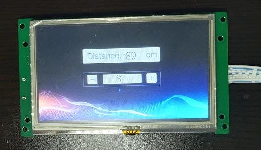
}In the case of no error in hardware connection, download the code into the STM32 development board, and the distance measured by the ultrasonic module can be seen in the STONE HMI display screen. In addition, the distance refresh time can be adjusted through the "+" and "-" buttons above the motor display module.
The article source: https://www.stoneitech.com/news/sharing/ultrasonic-module-test-with-stone-lcd-module.html
Code
Credits
Related products


Leave your feedback...