
Track It - Iot Based Delivery Tracking System

Made by pradeeplogu0 / Notifications / Vehicles / IoT
About the project
Will guide you to build an IoT based delivery tracking system with Qubitro API and RAK WisBlock.
Project info
Difficulty: Moderate
Platforms: RakWireless
Estimated time: 1 hour
License: GNU Lesser General Public License version 3 or later (LGPL3+)
Items used in this project
Hardware components

Story
As you know, we can track all of our delivery systems from food delivery to international shipments by using Google's geographical APIs and your mobile phone's GPS sensor readings. Let's consider you are going to get a shipment from an international courier service. You can track until it's reach to your nearby delivery station. After that, you can't. It only says “Out for Delivery”.

But if you are a guy like me, and you need to know the exact location of your shipment means you have to call your delivery agent and get the info about the package. There is no other option.
Solution:
In this project, we are going to build a system that can be attached with the delivery vehicle. And when your delivery guy took's your package, he will send a link to you. By that link, you can track your package in real time. So you don't need to call your delivery partner to track your package.
Hardware Requirements:
1. RAK5005-O,RAK112002. RAK1906,RAK1903,RAK19103. Arduino IDE for programming.
Let's start with simulation:
Before we are going to build a complete hardware system, let's simulate those by using simple python script and will try to show up the readings in the personal local website.
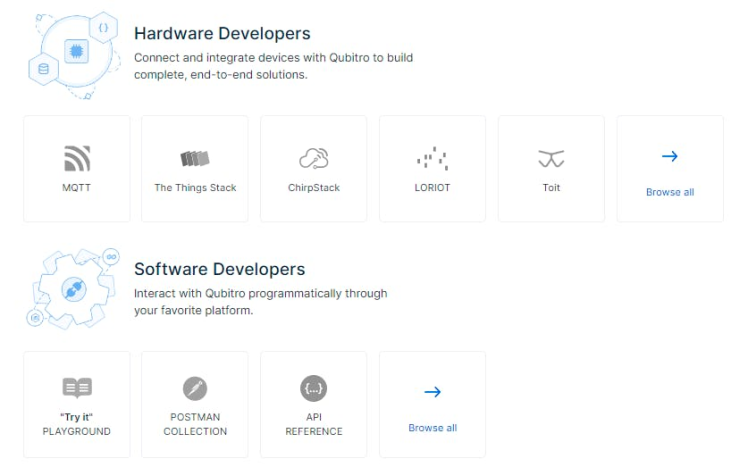
First, create a new MQTT project by using Qubitro. Follow these blogs to create a MQTT connection.
Soil Moisture Monitoring using ESP8266 and Qubitro
Once you create your MQTT project, next you need to connect your virtual device to Qubitro.
Here is the complete python code to simulate our real device data.
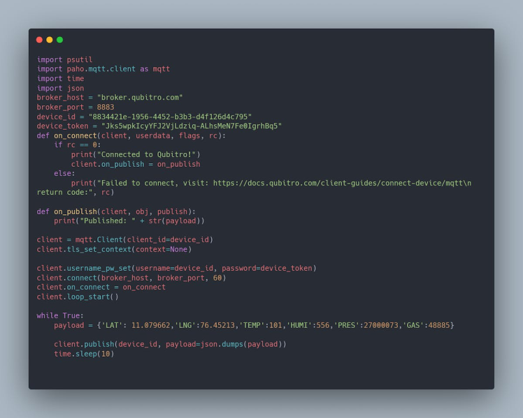
Don't forget to change your Device ID & Token in the above code before you are going to the run. You can see these expected results in terminal.

Then navigate to your Qubitro portal and look for the data.
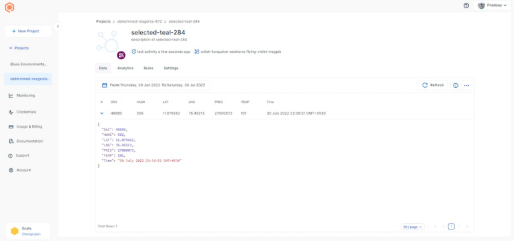
Now your virtual device is successfully connected and working. Then the next step is building a website. Qubitro has a powerful API feature, by using those APIs we can read and write device data and project information. Here is the guide to use Qubitro APIs.
Qubitro API Document
Local Website Deployment:
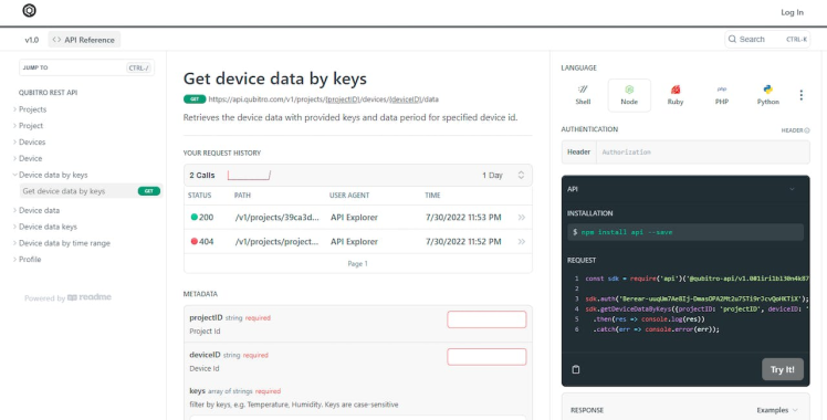
First, you have to get a particular API to read your device data. To get these, just go to the following URL.
Get device data by keys
You will be redirected to this page, and you need t enter some credentials into that.
Next, go to the credentials page in your Qubitro portal and copy the API key.
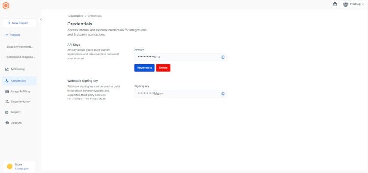
And paste that in the form of “Berear-API Key” in the auth tab of the API window.
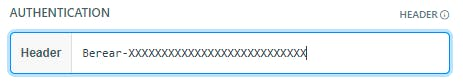
Then enter your Project I'd and Device Token. And just enter other parameters as follows.
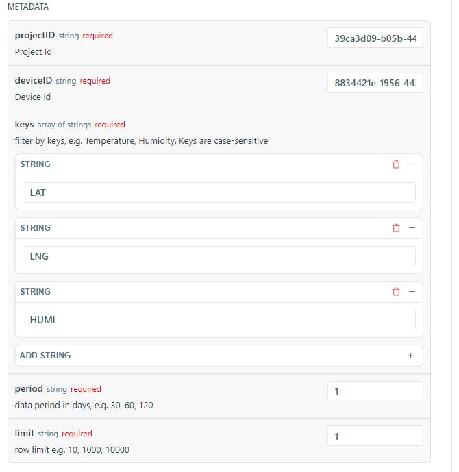
Next click on try it icon, it will return the corresponding readings.
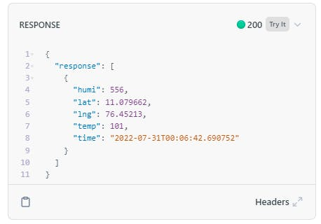
So, our API is now ready. Let's choose one of the language and generate the API.

Let's move to the web script side, we are going to use node JS. And the original script was forked from GitHub. Thanks to LintangWisesa for this one.
GitHub - LintangWisesa/Qubitro-GPS-Live-Tracking: A simple web app to show your device location (latitude & longitude) from Qubitro
And we added some items into that script. Download the script from the below GitHub link.
Qubitro-MQTT/Track IT, an IoT Based delivery tracking system using Qubitro and RAK Wireless WisBlock at master · pradeeplogu0/Qubitro-MQTTu0
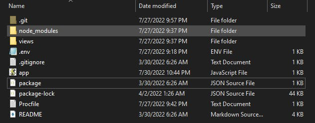
Then extract the files, you can see these files are inside the folder.
Next, enter these following comments in the terminal.
cd "Folder path" npm I
Open your.env file inside the downloaded folder and enter the credentials as per yours.
PROJECT_ID="your_qubitro_project_id"DEVICE_ID="your_qubitro_device_id"AUTHORIZATION="your_qubitro_auth"
Now you are all set. Make sure your virtual device script is running in the background. Then enter this command in the terminal window.
node app
It will be return like this.

Next, navigate to http://localhost:1234/ in your browser. You can see the below web page in your browser.
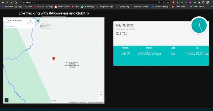
That's all, now your local server is up and running with Qubitro API and Python MQTT Device.
Let's integrate with Real Hardware:
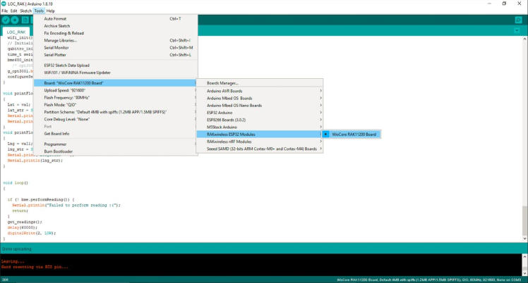
Open your Arduino IDE and compile this below code.
Update the code with your Device ID/ Token/ SSID/ Password
#include <WiFi.h>
#include <Wire.h>
#include <TinyGPS++.h>
#include <QubitroMqttClient.h>
#include <ClosedCube_OPT3001.h>     // Click here to get the library: http://librarymanager/All#OPT3001
#include <Adafruit_Sensor.h>
#include <Adafruit_BME680.h>       // Click to install library: http://librarymanager/All#Adafruit_BME680


Adafruit_BME680 bme;
TinyGPSPlus  gps;
WiFiClient wifiClient;
ClosedCube_OPT3001 g_opt3001;
#define OPT3001_ADDRESS 0x44
#define SEALEVELPRESSURE_HPA (1010.0)
QubitroMqttClient mqttClient(wifiClient);

float Lat,Lng;
double lux, luminosity;
String  lat_str , lng_str;

// Device Parameters change as per yours
char deviceID[] = "";
char deviceToken[] ="";

// WiFi Parameters change as per yours
const char* ssid = "ELDRADO";
const char* password = "amazon123";


void configureSensor()
{
  OPT3001_Config newConfig;
  newConfig.RangeNumber = B1100;
  newConfig.ConvertionTime = B0;
  newConfig.Latch = B1;
  newConfig.ModeOfConversionOperation = B11;
  OPT3001_ErrorCode errorConfig = g_opt3001.writeConfig(newConfig);
  OPT3001_Config sensorConfig = g_opt3001.readConfig();
}

void opt3001_read_data()
{
  OPT3001 result = g_opt3001.readResult();
  if (result.error == NO_ERROR)
  {
    luminosity = result.lux;
  }
  else
  {
    printError("OPT3001", result.error);
  }
}


void printError(String text, OPT3001_ErrorCode error)
{
  Serial.print(text);
  Serial.print(": [ERROR] Code #");
  Serial.println(error);
}


void bme680_init()
{
  Wire.begin();

  if (!bme.begin(0x76)) {
    Serial.println("Could not find a valid BME680 sensor, check wiring!");
    return;
  }

  // Set up oversampling and filter initialization
  bme.setTemperatureOversampling(BME680_OS_8X);
  bme.setHumidityOversampling(BME680_OS_2X);
  bme.setPressureOversampling(BME680_OS_4X);
  bme.setIIRFilterSize(BME680_FILTER_SIZE_3);
  bme.setGasHeater(320, 150); // 320*C for 150 ms
}

void get_readings()
{
  Serial.print("Temperature = ");
  Serial.print(bme.temperature);
  Serial.println(" *C");

  Serial.print("Pressure = ");
  Serial.print(bme.pressure / 100.0);
  Serial.println(" hPa");

  Serial.print("Humidity = ");
  Serial.print(bme.humidity);
  Serial.println(" %");

  Serial.print("Gas = ");
  Serial.print(bme.gas_resistance / 1000.0);
  Serial.println(" KOhms");

  opt3001_read_data();

  Serial.print("Light = ");
  Serial.print(luminosity);
  Serial.println(" lux");

  printFloatlat(gps.location.lat(), gps.location.isValid(), 11, 6);
  printFloatlng(gps.location.lng(), gps.location.isValid(), 12, 6);

  unsigned long start = millis();
  do
  {
    while (Serial1.available())
      gps.encode(Serial1.read());
  } while (millis() - start < 1000);

  if (millis() > 5000 && gps.charsProcessed() < 10)
    Serial.println(F("No GPS data received: check wiring"));

  Serial.println();

  // Send telemetry
  String payload = "{  "TEMP":" + String(bme.temperature)
                   + ","PRES":" + String(bme.pressure / 100.0)
                   + ","HUMI":" + String(bme.humidity)
                   + ","GAS":" + String(bme.gas_resistance / 1000.0)
                   + ","LIGHT":" + luminosity
                   + ","LAT":" + lat_str
                   + ","LNG":" + lng_str
                   + "}";
  mqttClient.poll();
  mqttClient.beginMessage(deviceID);
  mqttClient.print(payload);
  mqttClient.endMessage();
  digitalWrite(2, HIGH);
}
void wifi_init() {
  // Set WiFi mode
  WiFi.mode(WIFI_STA);

  // Disconnect WiFi
  WiFi.disconnect();
  delay(100);

  // Initiate WiFi connection
  WiFi.begin(ssid, password);

  // Print connectivity status to the terminal
  Serial.print("Connecting to WiFi...");
  while (true)
  {
    delay(1000);
    Serial.print(".");
    if (WiFi.status() == WL_CONNECTED)
    {
      Serial.println("");
      Serial.println("WiFi Connected.");
      Serial.print("Local IP: ");
      Serial.println(WiFi.localIP());
      Serial.print("RSSI: ");
      Serial.println(WiFi.RSSI());
      break;
    }
  }
}

void qubitro_init() {
  char host[] = "broker.qubitro.com";
  int port = 1883;
  mqttClient.setId(deviceID);
  mqttClient.setDeviceIdToken(deviceID, deviceToken);
  Serial.println("Connecting to Qubitro...");
  if (!mqttClient.connect(host, port))
  {
    Serial.print("Connection failed. Error code: ");
    Serial.println(mqttClient.connectError());
    Serial.println("Visit docs.qubitro.com or create a new issue on github.com/qubitro");
  }
  Serial.println("Connected to Qubitro.");
  digitalWrite(12, HIGH);
  mqttClient.subscribe(deviceID);
}
void setup()
{
  Serial.begin(115200);

  //gps init
  pinMode(WB_IO2, OUTPUT);
  digitalWrite(WB_IO2, 0);
  delay(1000);
  digitalWrite(WB_IO2, 1);
  delay(1000);

  Serial1.begin(9600);
  while (!Serial1);
  Serial.println("GPS uart init ok!");

  // Initialize the built in LED
  pinMode(LED_BUILTIN, OUTPUT);
  pinMode(12, OUTPUT);
  pinMode(2, OUTPUT);
  digitalWrite(LED_BUILTIN, LOW);

  // Initialize wireless connectivity
  wifi_init();
  // Initialize Qubitro
  qubitro_init();
  time_t serial_timeout = millis();
  bme680_init();
    /* opt3001 init */
  g_opt3001.begin(OPT3001_ADDRESS);
  configureSensor();
}

void printFloatlat(float val, bool valid, int len, int prec)
{
  Lat = val;
  lat_str = String(Lat , 6);
  Serial.print("Latitude = ");
  Serial.println(lat_str);
}
void printFloatlng(float val1, bool valid, int len, int prec)
{
  Lng = val1;
  lng_str = String(Lng , 6);
  Serial.print("Longitude = ");
  Serial.println(lng_str);
}


void loop()
{

  if (! bme.performReading()) {
    Serial.println("Failed to perform reading :(");
    return;
  }
  get_readings();
  delay(60000);
  digitalWrite(2, LOW);
}
Once you have done the compilation, next connect your RAK Base Board with Core and Sensor modules as per the below image.
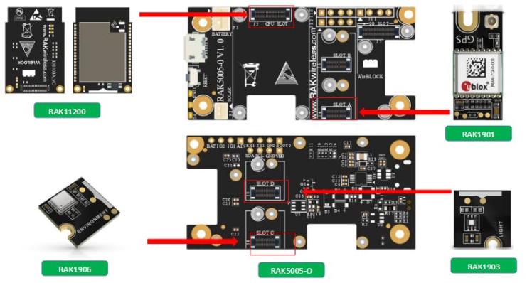
You have to connect GPS on Slot A, otherwise it won't work.
Then connect the board to your pc and select the right COM port and Board in your Arduino IDE and just upload.
Don't forget to short the BOOT and GND pins in the RAK Base Board to enable boot load function.
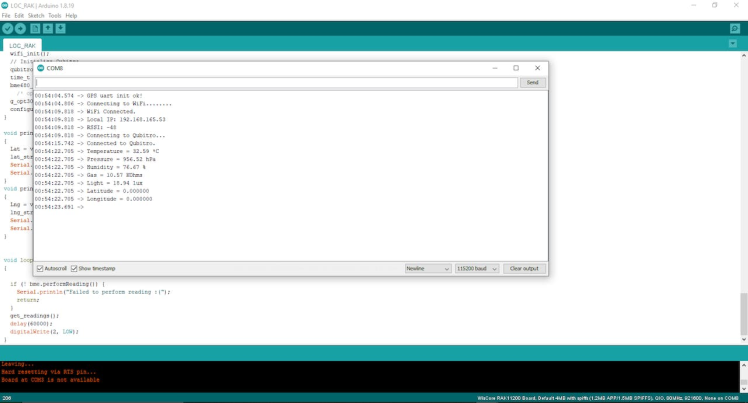
Here is the serial monitor results.
Then rerun the node JS script and just navigate to local web address.
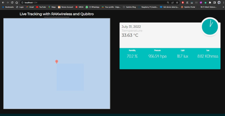
You can see your real time sensor readings into the webpage. Initially the GPS readings will be 0, 0 that's why there is no correct GPS location in the map. Also, I have added a piece of code to refresh the webpage for 5Sec, you can change that according to your need.
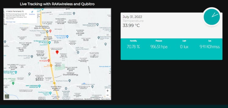
And I just installed this system in my friend's food delivery bag. Now his bag is IoT enabled ?.
Conclusion: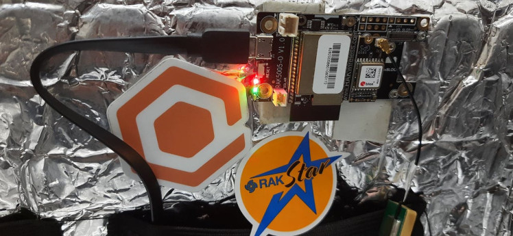
In this tutorial, we have shown how to build your own tracking system by using Qubitro API and Rak WisBlock modules. As we mentioned, Qubitro APIs are more powerful than you think. Also, the Rak WisBlock modules more user-friendly event though you don't have any wires to connect the modules, just click those on the slot that'a all. Finally, don't forget to join our Discord server. Thank You all!
Schematics, diagrams and documents
Code
Credits
Leave your feedback...