
Tiny Ml For Big Hearts On An 8-bit Microcontroller

Made by alex-miller / Artificial intelligence / Health
About the project
Predict the possibility of arrhythmias on an 8- bit Microcontroller, without sending the corresponding sensor data to the cloud.
Project info
Difficulty: Easy
Platforms: Arduino, Neuton Tiny ML
Estimated time: 1 hour
License: GNU General Public License, version 3 or later (GPL3+)
Items used in this project

Story
Story
In the course of the pandemic, the interest in creating more innovative medical devices has run high, as recent years showed how unpredictable the situation in healthcare can be. Never before have we faced such an acute need for masks, ventilators, oxygen cylinders, and other must-have devices to conquer the pandemic.All this has become a trigger to develop devices that can work autonomously for a long time, without access to the internet or cloud, just on batteries with ultra-low power consumption.
And most importantly, it's vital that such devices can be made by a wider range of people, even without in-depth technical skills. Perhaps, you’ve heard the story about two engineers from Lombardy who, at the peak of the epidemic in Italy, really saved their city as they began to print plastic valves for ventilators on 3D printers in their office and provided them to hospitals for free. The pandemic unified all, even those who were far from medicine before.
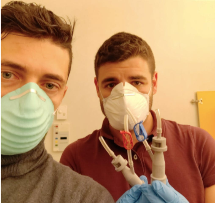
We took the picture here, and you also can read the full story from the same source.
I would also love to share a simple example, so to say - a super user-friendly concept. My goal is to show that any user without data science knowledge at all can make the smallest medical devices smarter (yes, even an 8-bit microcontroller) with the help of tiny ML solutions. Let’s go!
Introduction:
In this tutorial, I’d like to provide a vivid example of how the tiny ML approach can help to predict whether there is an impending arrhythmia or not, by running inferences on the microcontroller, without sending the corresponding sensor data to the cloud.
Let’s learn how to train and embed a compact machine learning model into the 8-bit ATmega2560 microcontroller. I deliberately chose such a memory-constrained and primitive microcontroller to show how simple and smart tiny ML devices can be.
Let's start by training a model. I took the original dataset from this resource: https://www.physionet.org/content/ptbdb/1.0.0/.
This dataset contains the signals of heart rate oscillations. The signals correspond to electrocardiogram (ECG) shapes of heartbeats for the normal case and the cases affected by different arrhythmias and myocardial infarction.
The goal was to detect abnormal heartbeats affected by arrhythmias and myocardial infarction based on electrocardiogram shapes. All the samples were cropped, downsampled, and padded with zeroes, if necessary, to the fixed dimension of 187.
The final element of each row denotes the class to which that example belongs.
Features, target, and target metric:
- 0...186 - sample description
- target - class of sample (0 - normal heartbeat, 1 - heartbeat affected by arrhythmias or myocardial infarction)
I combined all the cases into a CSV file and split it into a dataset for training (11, 641 rows), and a file to make an inference (2, 911 rows). Amplitudes of contractions of the heart muscle act as features for training the model. Here you can download preprocessed training and test datasets that we used for model training and prediction on new data.
Procedure
Step 1: TinyML Model Training
For the AI part of my project, I chose the Neuton Tiny ML platform. Having a special algorithm under the hood, Neuton automatically creates an optimal model in terms of accuracy and compactness. And the best part - the model doesn’t need to be compressed (which is perfect since I needed a very small model that would support the 8-bit architecture).
Next, I uploaded a CSV file and selected the column that should be trained to predict. In my case, this was a column where it was indicated whether there was arrhythmia on the cardiogram or not (1 - yes and 0 - no). Since I needed to embed the model into an 8-bit microcontroller, I selected such a setting in the interface (8-bit support) and started the training. Everything happened automatically.
The model was trained. To assess its quality, I chose the Area Under the Curve. My model turned out really small and accurate:
Area Under the Curve = 0.96, Model Size = 0.7 Kb, Number of Coefficients = 253.
Step 2: Embedding into a Microcontroller
After that, I downloaded the archive. It appeared immediately upon the completion of training.
The archive contained:
- Information about the model
Files with weight and meta-information in two formats, binary, and HEX, are used in the calculation process.
- Calculator
A set of functions that is an add-on to Neuton's algorithm providing inferences. For instance, the calculator includes functions for loading a model, calling call-back functions like transferring data, receiving calculation results, etc.
- Neuton Library
An algorithm that performs calculations.
- Implementation file
A file in which you can set the logic of actions for the results of calculations based on your business requirements.

Embedding into a Microcontroller
As you see, the archive folder contained all the necessary files, that simply could be transferred to the microcontrollers firmware project.
Since I did not have a real cardiograph, I streamed data from a computer. To do this, I developed a simple protocol that consisted of a header, a data section, and a checksum. The packet header had the following structure:
- typedef struct
- {
- uint16_t preamble;
- uint16_t size;
- uint8_t type;
- uint8_t error;
- uint8_t reserved[2];
- }
- PacketHeader;
I also provided packets with information about the number of model inputs, data transfers for performing predictions, as well as a report on the memory consumed by the calculator RAM and Flash and prediction time:
- typedef enum
- {
- TYPE_ERROR = 0,
- TYPE_MODEL_INFO,
- TYPE_DATASET_INFO,
- TYPE_DATASET_SAMPLE,
- TYPE_PERF_REPORT,
- }
- PacketType;
Then I developed a packet parser that would receive a stream of bytes from the USB-UART interface of the system board as input and, upon receiving a packet with the correct checksum, will activate the callback function for processing data packets.
Let's open the user_app.c file and create a neural network object:
- Static NeuralNet neuralNet = { 0 };
To initialize the neural network object, I called the CalculatorInit function. Upon successful initialization, the callback function CalculatorOnInit was called, in which I loaded the model from the model.c file.
For prediction, I called the CalculatorRunInference function. This function, in its turn, activates three callback functions: before and after the prediction, as well as the one that contains the results of the prediction. I filled them in: in the CalculatorOnInferenceStart function I started, and in the CalculatorOnInferenceEnd function I stopped the timer and calculated the minimum, maximum, and average value of the prediction time.
In the CalculatorOnInferenceResult function, I analyzed the class probabilities for the presence/absence of arrhythmia. Upon its absence, I turned on the green LED, but if the arrhythmia was detected, it was the red one. I connected the LEDs to GPIO ports 52 and 53 and sent prediction results to the computer.
In the sketch file, I initialized the neural network object, packet parser, GPIO, and UART ports:
- void setup()
- {
- pinMode(LED_RED, OUTPUT);
- pinMode(LED_GREEN, OUTPUT);
- led_red(1);
- led_green(1);
- initialised = (0 == app_init());
- initialised &= (0 == parser_init(channel_on_valid_packet, app_inputs_size()));
- Serial.begin(230400);
- }
And I wrote a code to call the parser when receiving data from the UART:
- void loop()
- {
- if (!initialised)
- {
- while(1)
- {
- led_red(1);
- led_green(0);
- delay(100);
- led_red(0);
- led_green(1);
- delay(100);
- }
- }
- while (Serial.available() > 0)
- parser_parse(Serial.read());
- }
Let's compile and upload the sketch to the system board (the "Verify" and "Upload" buttons). Success!
Step 3: Running Inference on the Microcontroller
To emulate the work of a cardiograph, I wrote a simple desktop application using the libuv library. The application performed the following actions:
- Sending the vector to the device on which the prediction took place
- Receiving a response from the device, regarding whether the sent cardiogram contained arrhythmia or not, and displaying the response
The interaction between the computer on which the application was running, and the microcontroller on which the prediction was performed occurred through the protocol that was described above in the article. Since the device was connected to the computer via a serial port, the communication took place in a binary format. I programmed the microcontroller so that when an arrhythmia was detected, I could see a red light, if not — then a green light lighted up. Find the link to a video showing how it works below.
Arrhythmia is not detected
Arrhythmia is detected
Note: When performing similar operations using TensorFlow, we spend most of the time on manual selection of the neural network architecture and its parameters, model conversion, compression, and reduction of the number of operations but I still didn’t manage to embed the model into an 8-bit microcontroller.
Conclusion
The pandemic has revealed that healthcare is in need of innovations, and I hope that a big boom in medical-edge devices awaits us. We need more devices that are not afraid of power and Internet outages. Devices that are very cheap and can be easily created by any guy in his office. Stay safe and have arrhythmia only from great love!
Code
Credits
Related products


Leave your feedback...