
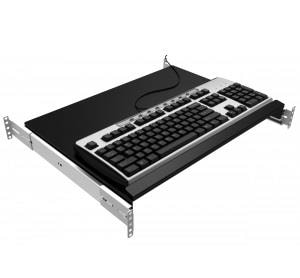
The Ultimate Wireless Keyboard Mark 2

Made by Gyro / 3D Printing
About the project
wireless keyboard but it's like a remote
Project info
Difficulty: Difficult
Estimated time: 1 week
Story
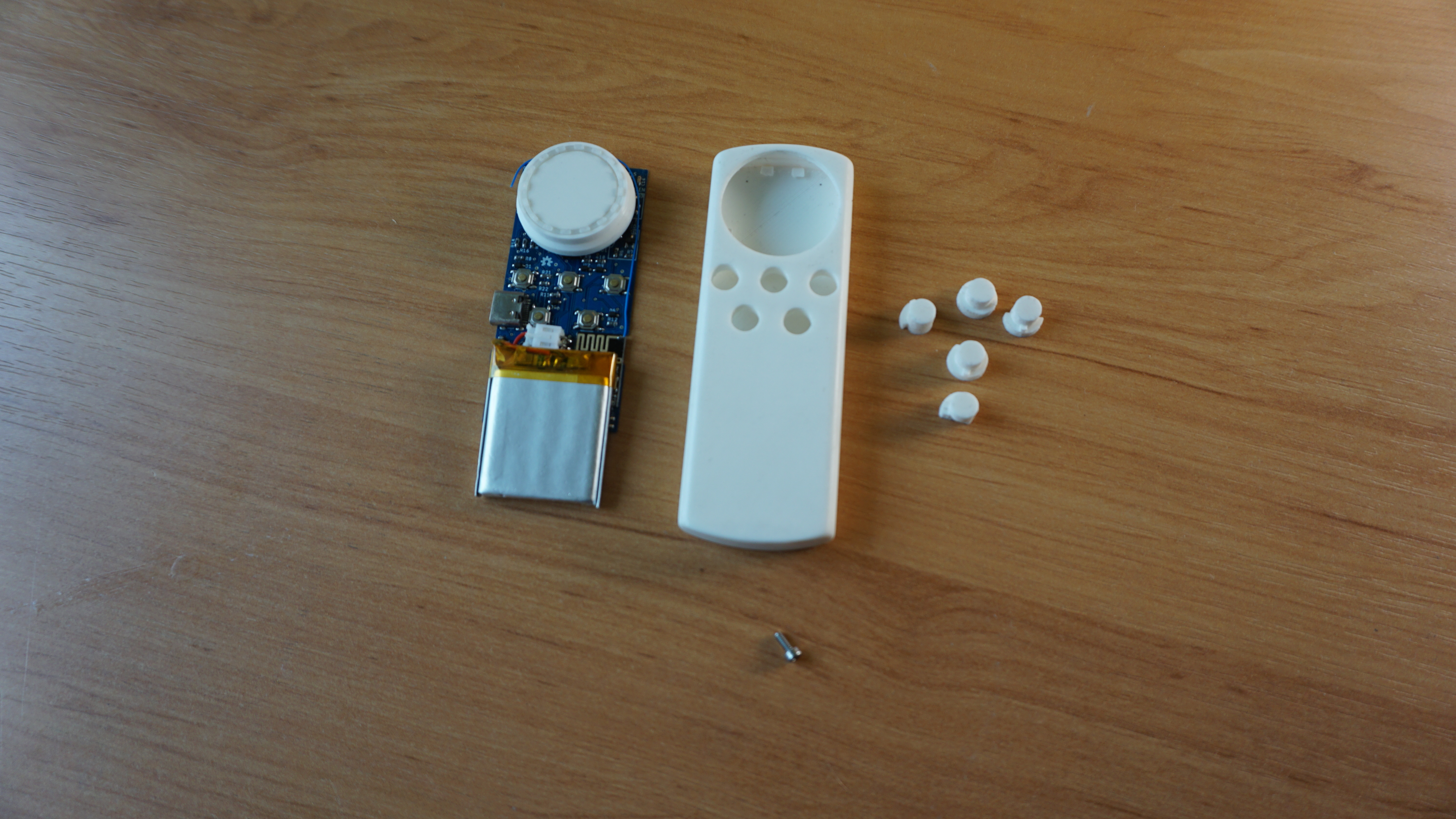
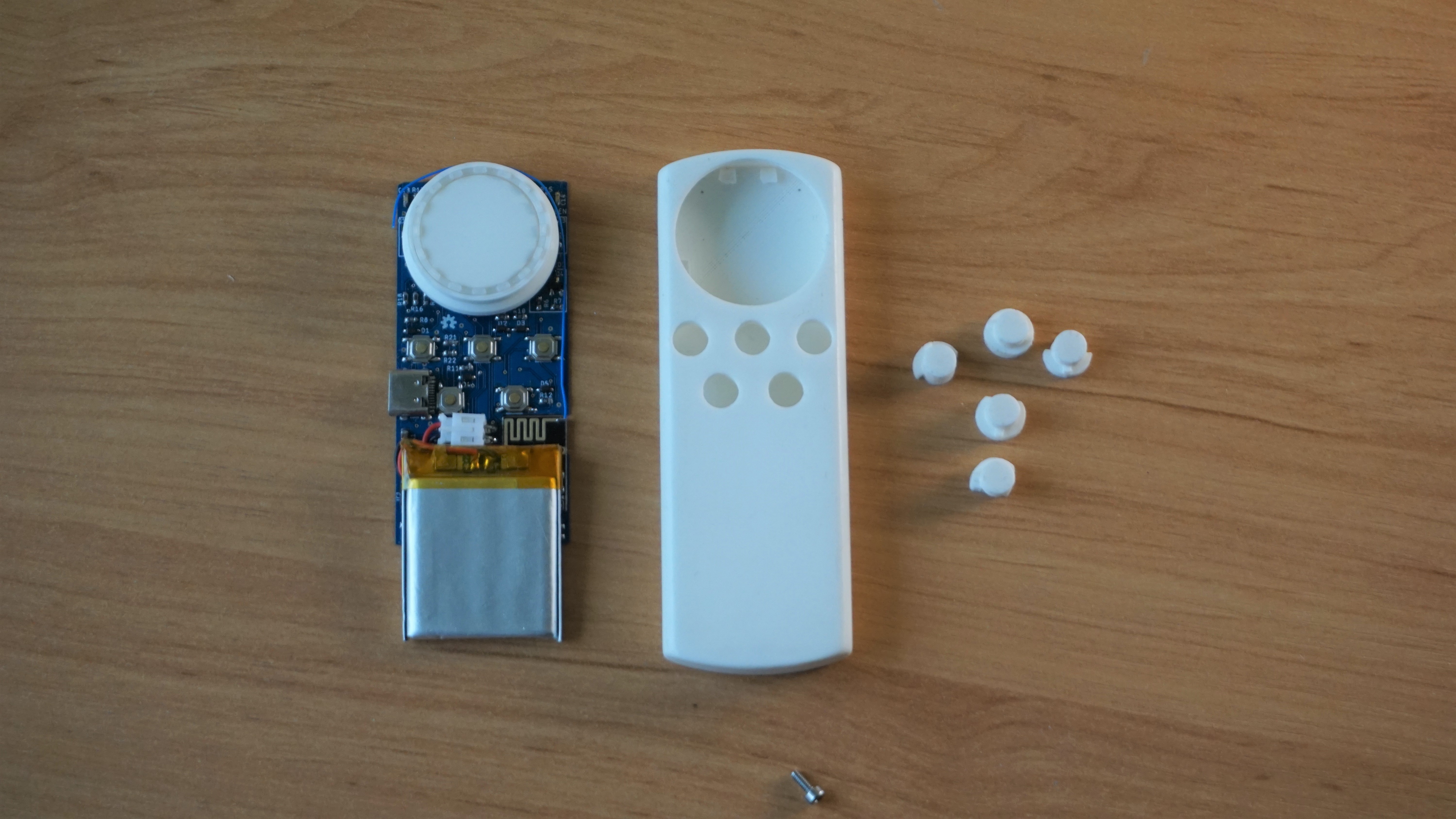
Step 1: Overview


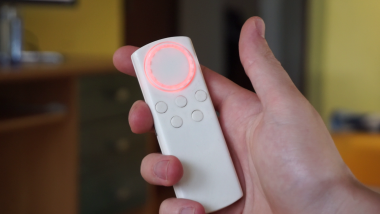
This remote is actually just a wireless keyboard. You can, of course, buy these but this one is simpler. It doesn't have over 80 buttons, just 7 and they all serve a purpose. Here are some other features that make it far better:
- Fully customizable buttons
- Multiple layouts - Separate layout for each app. Can be changed with a button
- wireless reprogramming
- 1-year battery life
- rechargeable battery with USB-C port
- low battery indicator
- simple customization app
- open-source
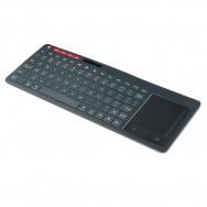
This whole project is just a solution to a minor inconvenience of watching youtube or movies on my PC. Trying to solve this problem I've tried several wireless keyboards but they are always big and often the button you need is behind a function key meaning you have to remember shortcuts and be looking at the keyboard when using it. There are also some apps that will turn your phone into a remote but you always have to unlock the phone and there is no tactile feedback.
Eventually, about 2 years ago I built a custom remote to solve all of these problems. It was however put together quickly and that took a toll on the quality and once it was done I realized, it still needed some more features.
original remote: https://www.instructables.com/id/Remote-for-PC-Youtube-and-Netflix/
This all led me to redo the original design as shown in the video. This remote is the result. Let me show you how you can build this yourself but keep in mind that this isn't exactly a project for beginners.
Make sure you check out the original remote I made because I'm going to be doing some comparisons to it. Not to mention that most of the hardware is the same, Just shrunk.
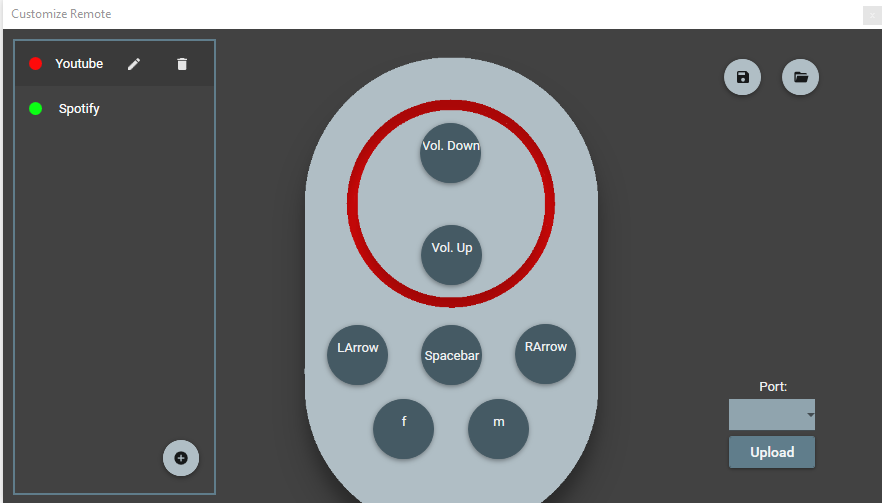
I might be a little bias here but I think this remote turned out perfectly. It's significantly smaller, the battery lasts for about 12 months and it's rechargeable with USB type C. There is no on/off switch anymore. Devices still recognize it as a standard keyboard meaning it'll work on any device that supports keyboards. On top of that, It supports multiple layouts with seamless switching between them. I currently have 2 layouts. One for youtube/VLC player and the other one for Spotify.
I've even written a windows app to customize these layouts. You only need the dongle to be plugged in and the remote gets programmed wirelessly.
Step 2: Tools and Materials
Tools:
- 3D printer - printed with PLA so any printer should do.
- soldering station / hot air station - Whichever you prefer. Most components are 0603 SMD size.
- Sanding paper - Not necessary but it makes the case look a lot better. 120, 320,1500 grit
Materials:
The electronics components are listed later and other than that you'll just need an M2x5 DIN 912 screw and M2 threaded insert. Mine is 4.1mm long but there is room for even longer one. That's all you'll need.
Step 3: The Electronics
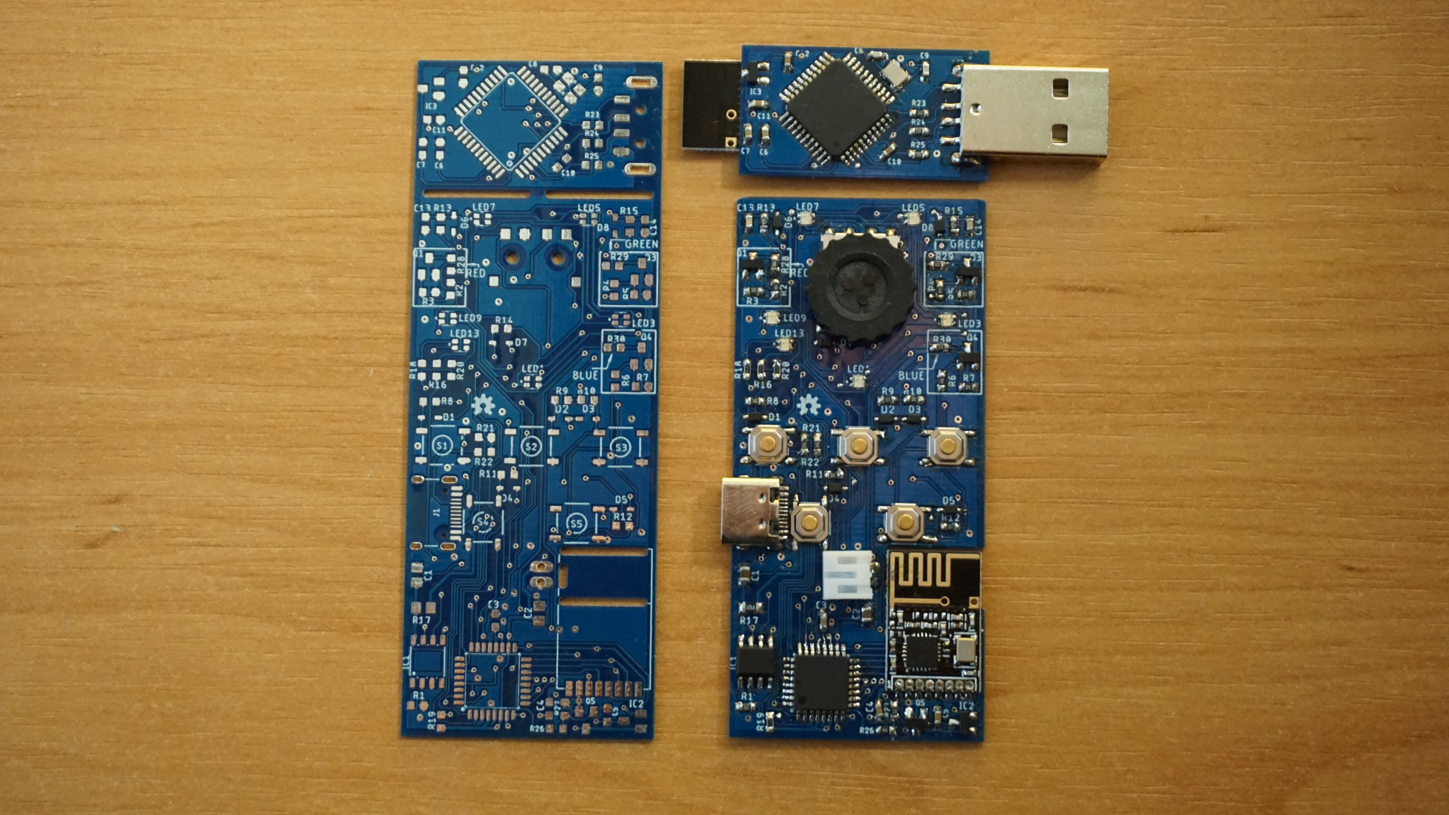
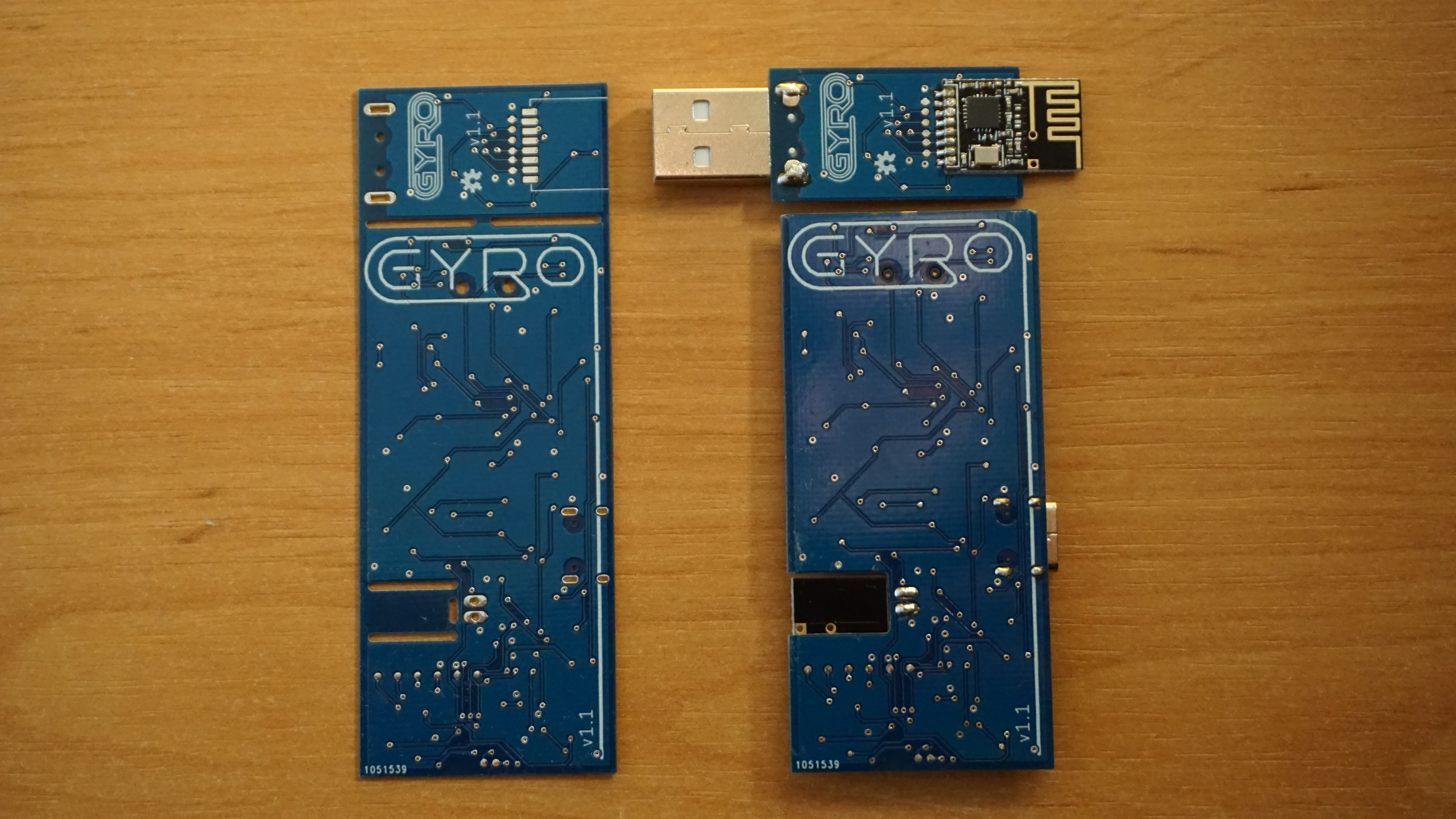
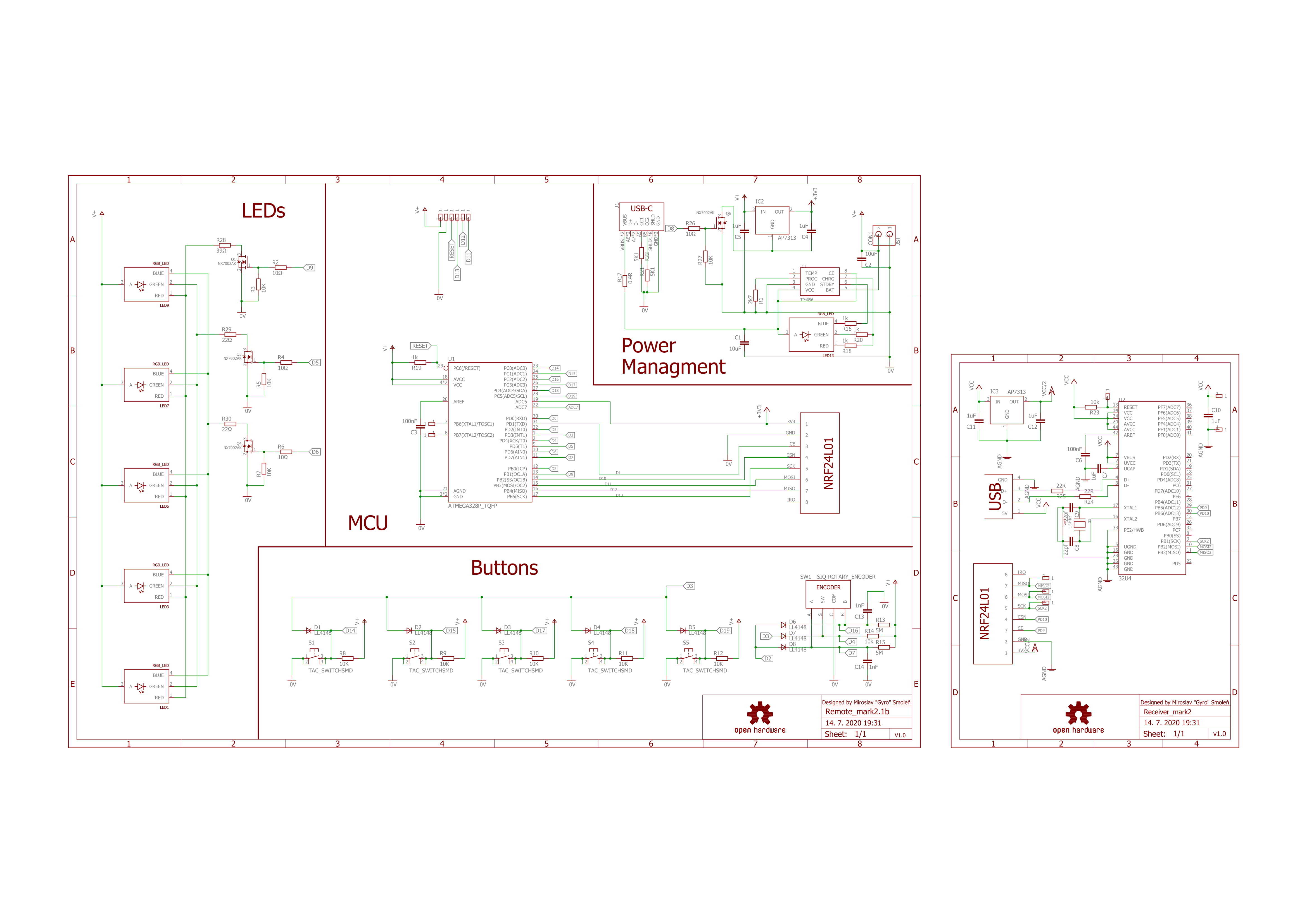
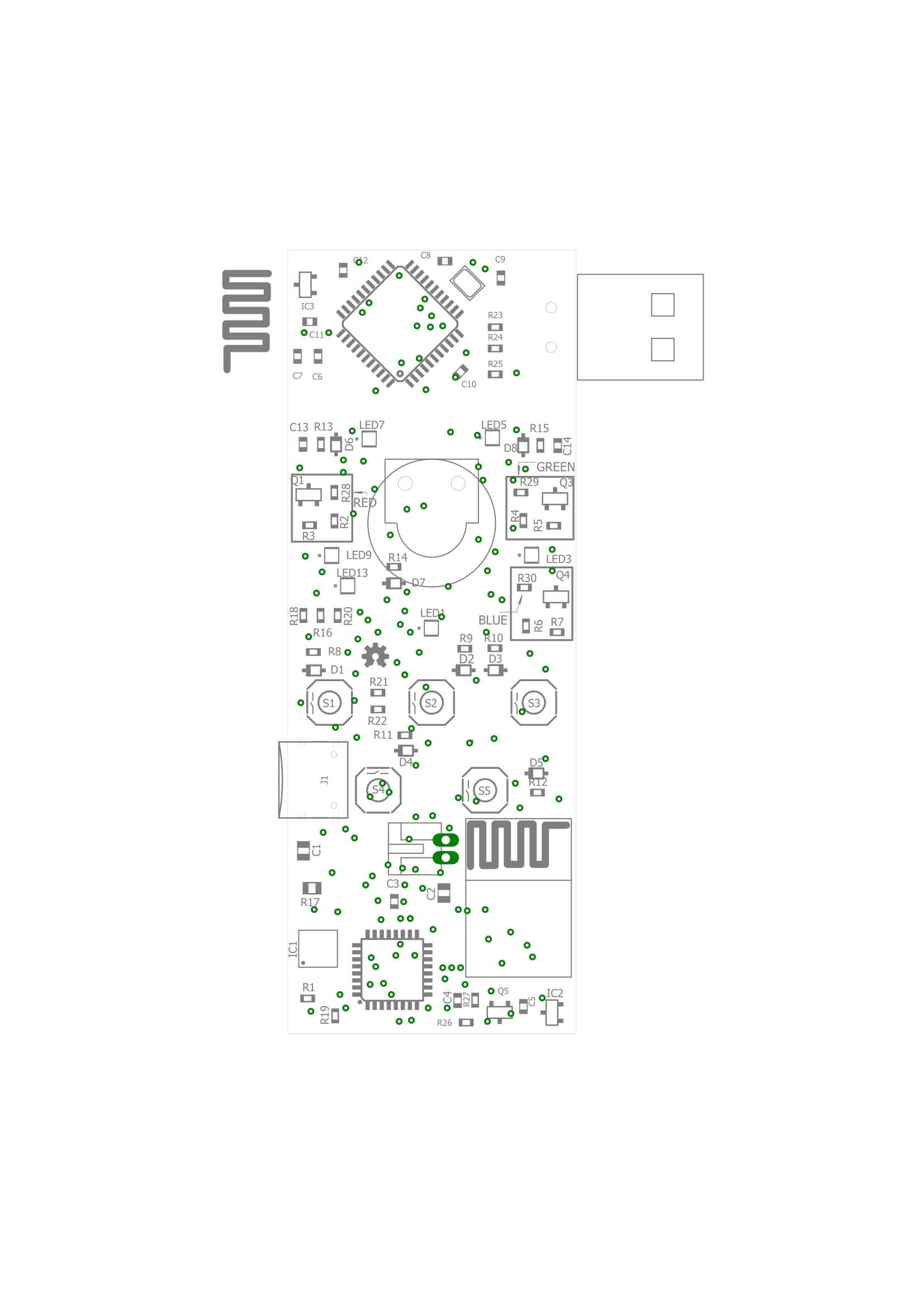
The project is designed to fit on one PCB which then breaks into two. You just need to break a few tiny tabs. I'd suggest getting the PCB professionally made as it is quite intricate. There are a lot of cheap Chinese companies that can do it for just a few bucks. I've included the Gerber files. They are all you need to provide to get one made. The PCB must be 0.6mm thick otherwise the case won't fit.
You can also get a stencil made to make the soldering easier but they are somewhat expensive. Especially if you're only making one remote. I got stencil with the first batch of PCBs and I made 10 PCBs in one day. When I reordered the PCB after fixing some mistakes. I decided not to get a stencil. Which I regret now because it takes me like 4-5 hours to solder a single PCB.
When it comes to putting it together. It's pretty straight forward. BOM(bill of material) includes all of the components you'll need to assemble the PCB. the placement of the components is shown on the board.pdf. There are just a few components that I wat to talk about.
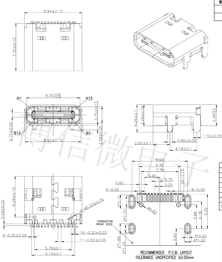
The USB type C is a trough hole 16 pin one. Since there are many types of these connectors I'm also including a picture from the datasheet and some links to make sure you have the right one. AliExpress, Amazon, Sparkfun
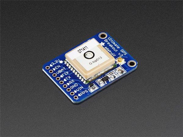
The transceivers also are known as NRF24L01 modules. There is a lot of Chinese manufacturers making these and recently they added smaller SMD version to the mix. Check out the links. AliExpress, Amazon
The battery I'm using is 500mAh Li-Po cell. the dimension are (H x L x W): 5mm x 35mm x 30mm. You can use a smaller one if you can't find the same one. The battery life should be fine even with half the capacity. This is where I got mine from.
Step 4: Programming
With the electronics done it's time to upload the Arduino program. This is usually a pretty simple task but I managed to complicate it. You're welcome :)
All of the programming was done on the 1.8.8 version of Arduino IDE. There are a few libraries you'll need:
-HID project(included in the windows app)
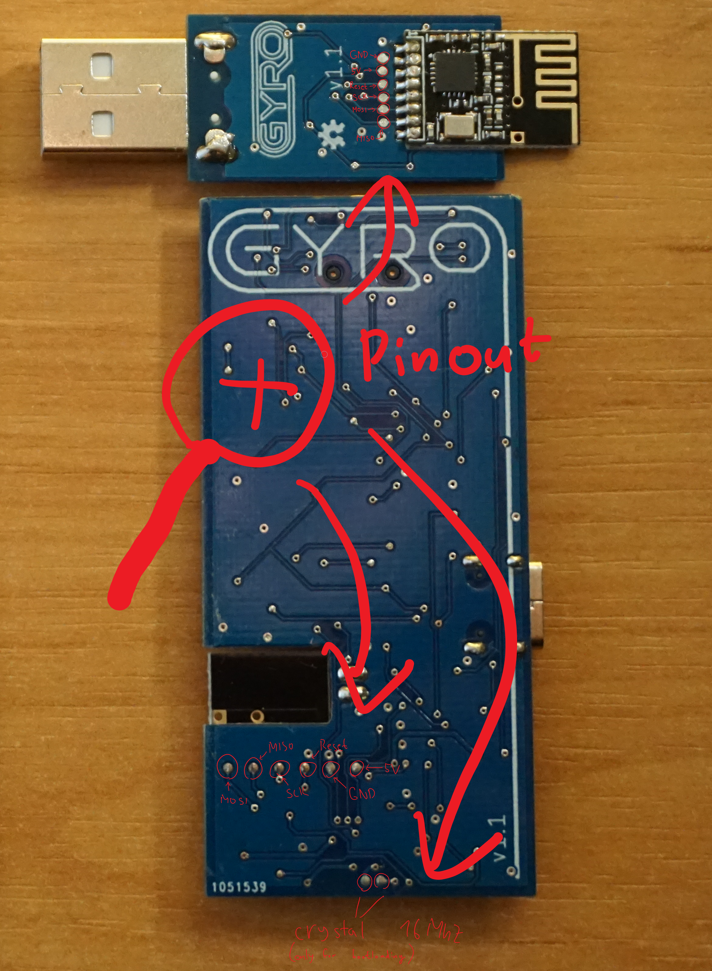
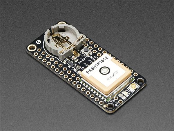
Each PCB has two Arduinos. Atmega32u4 for the receiver and atmega328p for the remote. While I said the remote can be programmed wirelessly it doesn't apply here. it's only the configuration that can be modified wirelessly. So both these microcontrollers must be first programmed using pads on the backside of the PCB. The pinout is shown in the picture. I personally decided to make a small programming jig since I was building more of them. I'm including the files for it here but it's pretty janky so keep that in mind.
When it comes to the wiring, the microcontrollers must be connected to an in-circuit serial programmer. I just used another Arduino nano. Here's a link if you want to do it the same way. Once wired there are 4 identical steps for both of the microcontrollers.
- Burn the appropriate bootloader
- Change fuse settings
- Load Address to the EEPROM memory
- Upload the actual program
1. Burning the bootloader
This process is also explained in the link above but essentially you're burning "firmware" telling the microcontroller what kind of Arduino it is. For the atmega328 we need special bootloader because we'll be using the internal clock. I Got it from here. For Atmega32U4 we can use the default one(Arduino micro). One other quirk I found was that the Arduino IDE would always fail to burn the bootloader for no apparent reason. I solved this by using an older version of the IDE. 1.0.5 to be specific.
2. Changing fuse settings
In short, fuses on a microcontroller are its fundamental settings. There is one option we need to change. The EESAVE fuse. By default, uploading a new program also deletes the EEPROM memory. Changing this fuse will mean the EEPROM will be kept even after we reprogram it. This is crucial as the address of the remote and receiver is saved on the EEPROM. The actual program for the remote and receiver doesn't contain their addresses.
Let's talk about how to do it. We'll need to use avrdude which is a tool that comes standard with Arduino IDE and I'm again using version 1.0.5 here. Unfortunately, it has no graphical interface so you'll have to use the command line. Open CMD and navigate to avrdude which is usually in the Arduino IDE folder at hardware/tools/avr/bin/
For both microcontrollers we'll be changing the HIGH fuse to the following:
original is 0xDA changed to 0xD2 -atmega328p
original is 0xD8 changed to 0xD0 -atmega32u4
These are the actual commands I used but you'll have to adjust the path:
G:Mirkoarduinoarduino-1.0.5hardware/tools/avr/bin/avrdude -CG:Mirkoarduinoarduino-1.0.5hardware/tools/avr/etc/avrdude.conf -v -cstk500v1 -PCOM11 -b19200 -patmega328p -U hfuse:w:0xd2:m
G:Mirkoarduinoarduino-1.0.5hardware/tools/avr/bin/avrdude -CG:Mirkoarduinoarduino-1.0.5hardware/tools/avr/etc/avrdude.conf -v -cstk500v1 -PCOM11 -b19200 -patmega32u4 -U hfuse:w:0xd0:m
3. Loading address to EEPROM
When I say I address I mean the communication pipe for the NRF24. The only reason I decided to give each remote unique address is that if you have more than one in a room they won't trigger each other. The address is saved in EEPROM memory meaning it won't get erased even if the battery is unplugged. Since we changed the fuse setting in the previous step, The address will be saved even when uploading a new program. To write the address to memory you'll need to upload the eeprom_writer sketch. In the sketch, you may customize the address by changing the n1, n2, n3 variables. The sketch must be uploaded to both microcontrollers.
To upload the sketch use the ICSP as described before. I have once again stumbled to a problem with the IDE. I was able to compile the sketch in the 1.8.8 version but it wouldn't upload. In the 1.0.5 version, it wouldn't compile but uploading worked great. My workaround was to generate a hex file with the 1.8.8 version and then upload it with the avrdude of the 1.0.5 IDE. The process is discussed more here.
4. Uploading the final program.
Lastly, you just have to upload the sketches for the remote and receiver. You can actually plug the receiver in with it's USB port and do it that way. For the remote, you'll still need the in-circuit serial programmer. And the process of generating hex file and using avrdude described above applies here too. Once you have the programs uploaded it's done. they should be working. You can now configure it how you like it.
The Windows app can now be used to customize the buttons how you like it. Have fun :)
Step 5: The Case
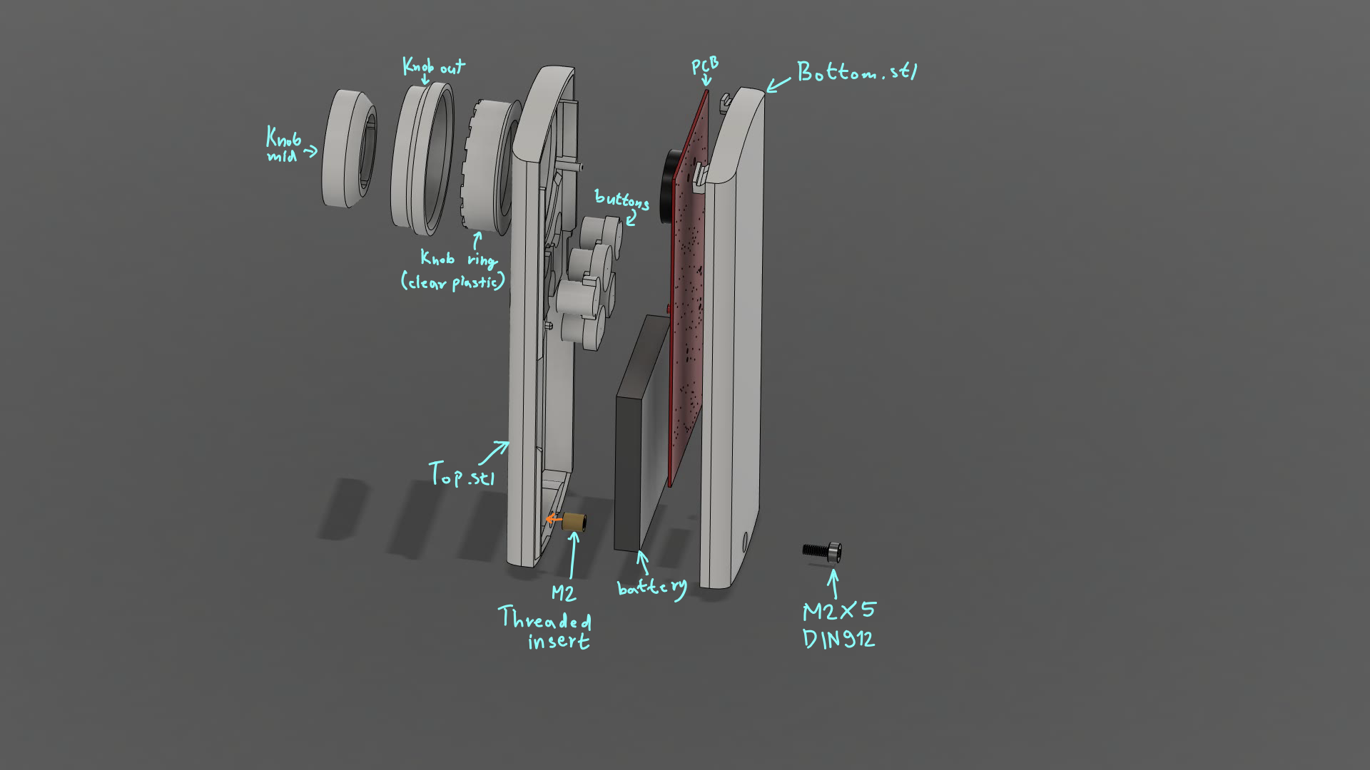
You can just print all of the files, put it together, and call it a day. Just don't expect the results you see in the pictures.
I printed my remote on Creality CR-10 with 0.1mm layer height. The buttons have a small hole running through the middle which means slicer will create a perimeter around the outside and the middle. I also made the perimeter thicker so there is no infill. this made the buttons really clean after sanding them.
The top and bottom parts were both printed with the large face touching the buildplate. I have also added support material since the overhangs are a bit too steep. everything was printed in white PLA except for the ring light on the knob which was printed in clear PLA.
The knob is superglued together which is the only part requiring glue. To sand the case, I put it together and sanded both halves at once. That assures there won't be any gaps between them later. I started with 120 grit. After most of the layer lines were gone I switched to 320 grit which was then followed 1500 grit for a matte finish. It's not perfect but since I didn't use any paint it should be more resistant to scratches. The same sanding technique was used for the knob and buttons as well.
Actually, I lied. I used glue on the dongle as well. To be completely honest I didn't put much effort into the dongle and neither should you. Just slap it together.
CAD, enclosures and custom parts
Credits
Related products


Leave your feedback...