

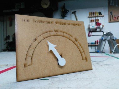
The Internet Speed-o-meter

About the project
A physical display to show how much of your Internet connection is being used.
Project info
Difficulty: Moderate
Platforms: Espruino
Estimated time: 2 hours
License: GNU Lesser General Public License version 3 or later (LGPL3+)
Items used in this project
Hardware components

View all
Software apps and online services
Hand tools and fabrication machines
Story
Introduction
This is a little project to monitor the usage of a building's internet connection. There was not easy way for someone who was technically minded to monitor this never mind making the the end users. This is an answer to that problem. The hardware communicates with the central router/firewall, asks how much data has passed thought it, subtract that from the last figure it was told, and then moves a physical arrow to show that figure to everyone. Although it is called the "Speed-o-meter" in the great style of Wallace and Gromit it should more accurately be thought of as a percentage of bandwidth usage meter.
Step 1 - Programming the microcontroller
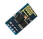
At the heart of the system is an ESP-01 module. Any ESP6266 based development board or Arduino with networking should run the code with little or no modification.
I am going to assume that you are able to load the code from this listing to the microcontroller. If you don't know how to do that you can find plenty of tutorials online.
You will need to change three settings in the supplied code. First you will need to replace {wifi_ssid} and {wifi_password} with your wifi details. Next you need to change
{top_connection_speed} to the maximum speed of your connection. Note that this needs changing in two locations.The current code will monitor both upload and download rates and pick the highest to show. If your connection is
asymmetric (has a different upload rate to your download rate) then you can tweak the updateServo() function to reflect this. This is completely optional and only for programmers how are obsessive compulsive about accuracy. Basically if you are like me.Once these settings have been changed and the code uploaded you are ready to go on to the next step.
Step 2 - Assembling the hardware
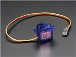
Rather than create a new circuit board or have many cables all crammed together at the back I decided to "hack" the fairly common ESP-01 adapter. This has the main advantage of regulating the power down from the 5V supply we are going to use down to the 3.3v required by the ESP-01 module. If we use the TX pin as a data pin for controlling the servo then by pure luck the GND/SVV/DATA pins on the adapter are in the correct order for a standard servo.
I removed the RX pin to reduce the risk of the servo being plugged in incorrectly but this is optional.
It is worth noting that the ESP8266 sends some serial data is sent out of the TX pin on boot and that can crash some servos. If this is the case you will need to modify the design to use the RX pin instead, or try another servo.
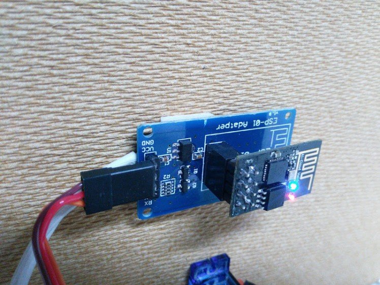
As we have used the VCC and GND pins to connect the servo we need to inject power another way. This is a simple hack with the power cable being soldered on the underside of the board.
The power supply is a 5v "wall wart" with a power cord on. I extended it with some speaker cable but the original was long enough for most projects.
Step 3 - Assembling the display
The last significant step is to add the electronics and mechanics to a board and create the physical display.
This listing has some CAD drawings that can be used to laser cut and board and arrow although this is where your creativity can flow. Why not create your own design?
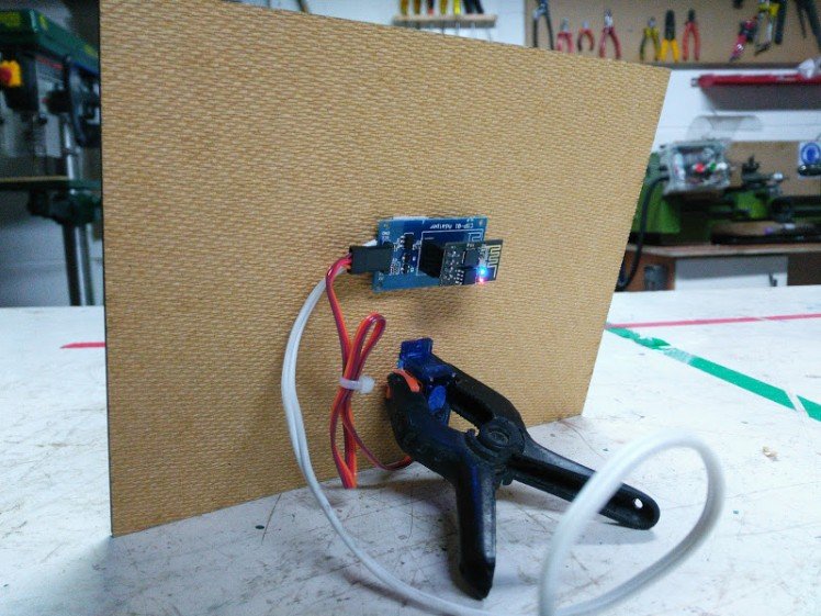
Finally the project needs mounting somehow. You could mount it on the wall or place it on the mantelpiece. I have used picture frames and plate stands to do this with other projects, but for this on I decided to simply add a workshop clip to the back to hold it upright on the workshop shelf.
Step 4 - Sit back and enjoy
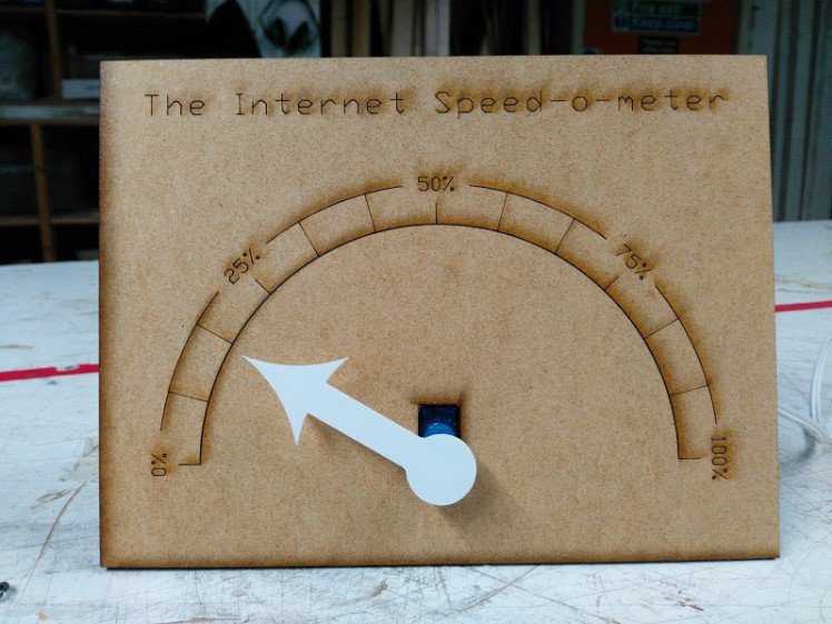
That is it all done. When you power it up it will take a free seconds to settle down and then you will see how much data is going through your network. If not a lot is happening then run a speed test and see how much of your bandwidth you can use.
Leave your feedback...