
Sony Spresense 120/240 Volt Power Supply Module

Made by Jade7272 / Home Automation
About the project
120/240V AC or 30V DC power supply module for the Sony Spresense Expansion Board. Plug and power your projects for real world.
Project info
Difficulty: Difficult
Platforms: Sony
Estimated time: 7 hours
License: Creative Commons Attribution-ShareAlike CC BY-SA version 4.0 or later (CC BY-SA 4+)
Items used in this project

Story
**Important Note**
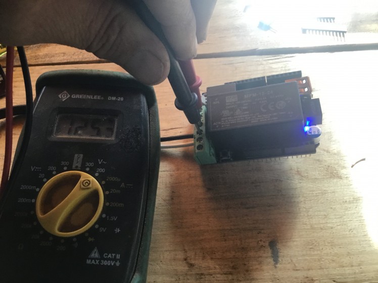
Before starting this project you should be aware that you are hooking 120/240 volts AC to your shield. These voltages could be deadly and or cause a fire if you overload the relay or solder it wrong. You can also be seriously hurt if you don’t use proper work and safety ethic. Do not work on the Shieldwhile it is plugged into power. You should only have the power plug plugged in if it is inside a plastic or insulated box and ready to be tested and/or completed. TEST THE SHIELD BEFORE YOU PLUG IT INTO the Expansion Shield using a voltmeter to ensure that 5 volts DC is the output on the VIN pin of the shield. Be very careful not to come into contact with the high voltage side of the shield. As you can see from the included images, I used silicone to isolate the power pins on the underside of the shield. Hot glue would work as well.
*****************************************************************************
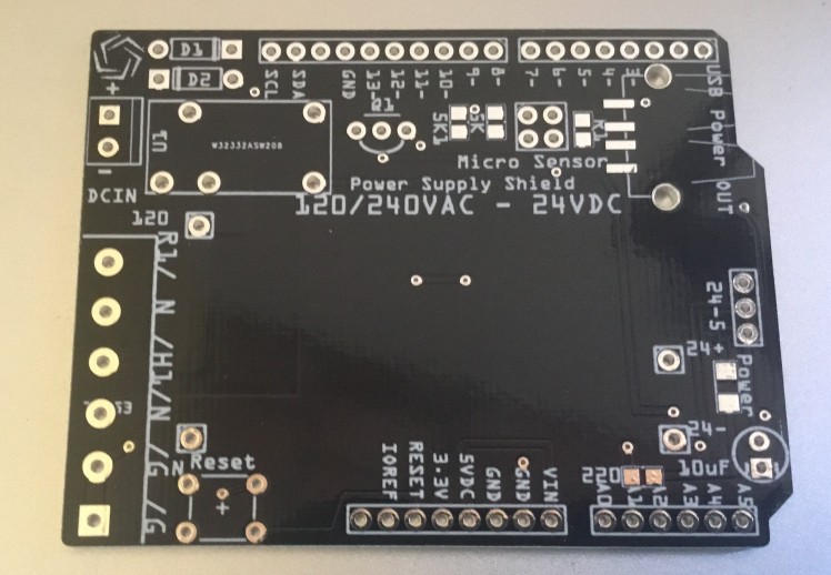
This shield has some notable features. It not only converts 120/240 to a useable DC voltage, it also has a DC input good for 30 volts DC and a relay that is activated from D6 that can either be used as a 120V relay or a DC relay depending on how it is powered. It is good for 5 Amps, which is more than enough seeing that higher loads will require another contactor to be driven from the relay. I have also included my patended I2C micro sensor inputs shields, which can be either a (a) power sensor, (b) accelerometer, (c) altimeter (d) humidity temperature sensor. It also has a USB power out to power other USB devices such as an Arduino or Particle, etc. Specification sheet so the various sensors can be found in the below attachments as well as the Gerber files and Fritizing files for the shield.
This projects is in 2 parts:
1. Shield design and soldering
2. Shield programming with the Sony Spresense
 Power supply module
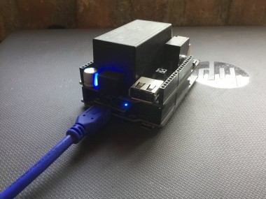
I designed the shield to fit on the Sony Spresense Expansion Shield, Arduino R3 or the Arduino Mega. I used a commercially available through-hole design and certified power supply module for this project.
I used a program called Fritzing ( http://www.fritzing.com) as they have a pretty good Arduino shield blank to work with and the program is easy to use for beginner PCB design.
I ordered the PCBs from (http://www.PCBway.com) from China. The basic cost for the board is $5.00 plus shipping for 10 boards. Which leaves some room for mistakes. The board is easy to solder as there aren't many solderable pieces.
For the SMD parts, I use OSHstencils.com for my stensils.
 AC/DC power supply shield
 120V in
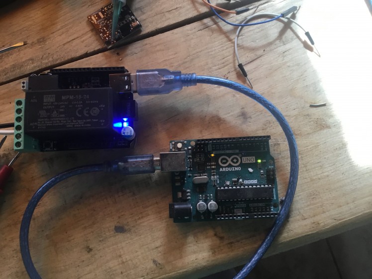 Powering an Arduino from USB out port
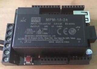
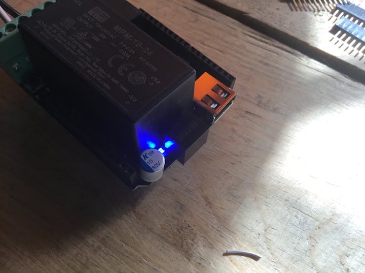 Rear of module
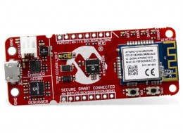
Sony Spresense
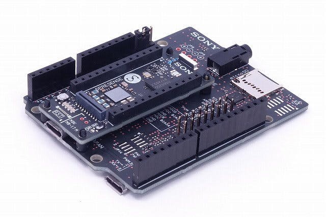 Sony Spresense with Expansion Shield
What is Spresense?
SPRESENSE™ is a low-power board computer for the IoT that is equipped with a GPS receiver and supports High-Resolution Audio codecs. The board allows for IoT versatility and can be developed for a vast range of uses, such as a drone utilizing the GPS and high-performance processor, a smart speaker utilizing High-Resolution Audio recording and playback as well as the built-in full-digital amplifier, or a low-power time-lapse camera utilizing the camera interface. SPRESENSE™ will make the IoT smarter and more efficient.
High-precision Positioning FeaturesUltra-low power consumptionMultiple GNSS systems supported: GPS, GLONASS, SBAS, Galileo, and BeiduAdvanced High-Resolution Audio features192 kHz/24 bit High-Resolution Audio codec 192 kHz A/D converter8 channel microphone inputs (for digital microphones)Full digital amplifier with BTL stereo outputExtensive computing powerHexa-core ARM® Cortex®-M4F
Configuring and programming your Sony Sprense Board Sony IDE
Download and install dependencies and programs to your Raspberry Pi here:
Once everything is installed follow the instructions in Installing the Sony IDE and plug your board in. Then flash the operating system according to the Instructions.
Configuring and programming your Sony Sprense Board Arduino IDE.
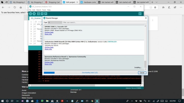 Installing necessary Arduino code and boot loader
Once you have finished all the installs for either the Arduino or the Spresense IDE next is the programming.
There are three sensors and the WiFi module to program in.
1. {LTC2945} Mounted on the power shield sensor to give current and voltage reading of the power inputs, communicating by I2C.
2. {MPL3115A2} Mounted on the WiFi shield to give altitude and temperature readings, communicating by I2C.
3. {CCS811} Mounted on the WiFi shield to give humidity and temperature readings, communicating by I2C.
4. {ATWINC15x0} WiFi board mounted on the WiFi shield and communicates via MOSI/MISO.
Schematics, diagrams and documents
Credits
Related products


Leave your feedback...