


Solar-powered Rfid Water Vending Machine Using Esp32 For Off

Made by chanchaldada / IoT
About the project
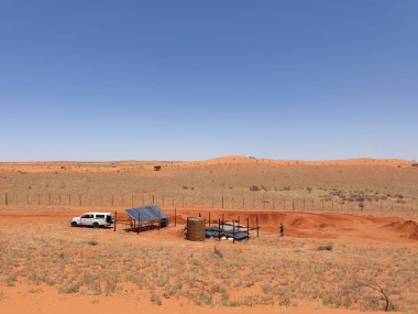
We’ve built vending machines before, but this one had a twist — no grid connection, no cellular towers nearby, and a budget that ruled out industrial PLCs or proprietary controllers.
Project info
Difficulty: Expert
Platforms: Raspberry Pi, Espressif, JLCPCB
Estimated time: 5 hours
License: MIT license (MIT)
Items used in this project
Hardware components



Story
The Problem: Clean Water Access Without Grid Power
A non-profit approached us in early 2024 with a straightforward request: design a water vending machine that could operate in rural villages with no reliable electricity. The machine needed to dispense filtered water in exchange for RFID-based credits, run entirely on solar power, and survive dust, heat, and monsoon rains. The client wanted something maintainable by local technicians with basic electronics knowledge.
Our answer: an ESP32-based system running on a 20W solar panel with a 12V 20Ah LiFePO4 battery, communicating via RFID for user authentication and storing transaction logs on SD card. No cloud dependency, no cellular modem, just reliable offline operation.
System Architecture Overview
Here’s what we settled on after three design iterations:
Core components:
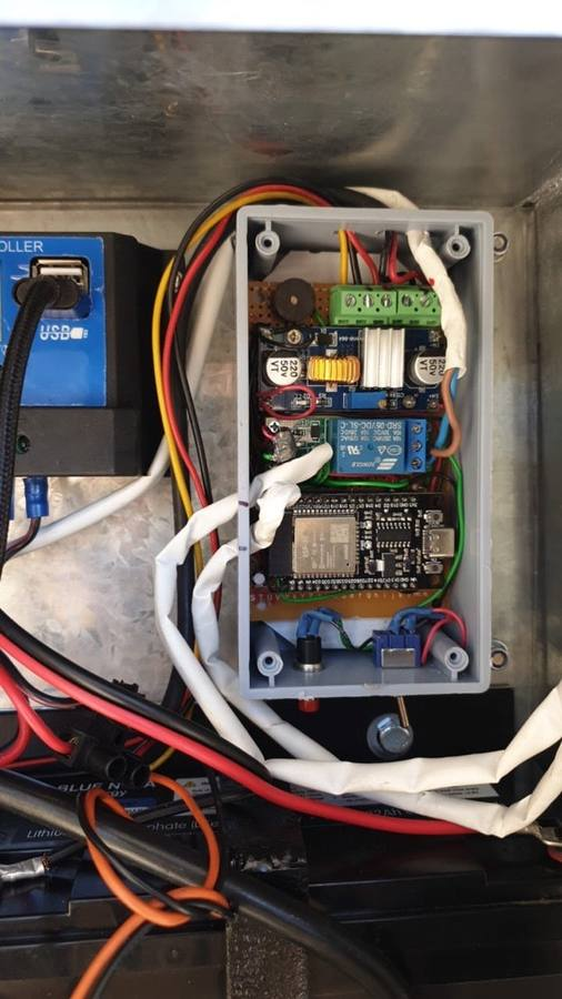
- ESP32-WROOM-32 — main controller, handles RFID reading, solenoid valve control, display updates, and power management
- MFRC522 RFID module — reads 13.56MHz MiFare cards, 3cm read range
- 12V normally-closed solenoid valve — controls water flow, draws 500mA only during opening
- 0.96" OLED display (SSD1306) — shows credit balance, water dispensed, battery level
- INA219 current sensor — monitors battery charge/discharge for low-battery shutdown
- DS3231 RTC — timestamps transactions for auditing
- MicroSD card module — stores transaction logs in CSV format
Power system:
- 20W polycrystalline solar panel (36 cells, 22V open circuit)
- 12V 20Ah LiFePO4 battery with BMS (much safer than lead-acid for indoor use)
- Generic MPPT charge controller (we tested two, the 10A model worked best)
- 5V 3A buck converter to power ESP32 and peripherals
Mechanical:
- 20-liter HDPE water tank with float switch for level sensing
- 12V diaphragm pump (3L/min, 60W) for pressurizing the system
- Stainless steel spout with drip tray
- IP65 enclosure for electronics
- RFID reader mounted behind 3mm acrylic window
Total BOM cost came to roughly $180 per unit at prototype quantities. The client ordered 50 units after testing.
Firmware Design: Why We Chose ESP32 Over Arduino
This wasn't a simple "read RFID, open valve" job. We needed:
- Deep sleep power management (system idle current < 100µA)
- Real-time clock synchronization
- Transaction logging with error recovery
- Battery monitoring with graceful shutdown
- Over-the-air firmware updates for field maintenance
An Arduino Uno would've run out of flash by the time we added SD card writing and JSON parsing. The ESP32 gave us dual cores, 4MB flash, 520KB SRAM, and hardware support for I2C, SPI, and UART simultaneously.
We wrote the firmware in C using ESP-IDF v5.1, not Arduino. Here's why: ESP-IDF gives us direct control over power management, deep sleep wake sources, and interrupt handling. The Arduino framework adds overhead we couldn't afford at 80MHz with a 20W solar budget.
Key firmware decisions:
1. Deep sleep strategy: The ESP32 sleeps for 5 seconds between user interactions. When a user taps their RFID card, the MFRC522's IRQ pin wakes the ESP32 via GPIO interrupt. Total wake time per transaction: ~800ms. This gives us 30+ days of standby on a full battery with no solar input.
2. Transaction atomicity: We write each transaction to SD card before opening the valve. If power fails mid-dispense, the system knows exactly how much water was credited. We use a simple state machine — `IDLE -> AUTH -> DISPENSE -> LOG -> SLEEP` — with each state saving its progress to RTC-backed SRAM.
3. Battery management: The INA219 reads battery voltage every 10 seconds during idle, and every second during dispensing. Below 11.8V (20% SoC for LiFePO4), the system refuses to open the valve and shows "Low Battery — Charging" on the OLED. Below 11.2V, it enters a deeper sleep mode (RTC-only, no RFID wake) until the solar panel brings voltage back above 12.5V.
4. RFID credit system: We use the MiFare Classic 1K card's sector 1 (blocks 4-7) to store credit balance as a 4-byte integer. Each dispense decrements the balance on-card, so the card itself is the wallet — no server required. The ESP32 reads the card, checks CRC, deducts 1 credit (200ml water), writes back, then opens the valve for 6 seconds.
PCB Design: Power Isolation and Noise Management
The first prototype had a problem: the solenoid valve's inrush current caused the ESP32 to brown out. The 5V buck converter couldn't handle the transient, and the ESP32 reset mid-dispense.
We redesigned the PCB with separate power rails:
- Rail 1 (always-on): 5V → 3.3V LDO (AMS1117-3.3) for ESP32, RTC, and RFID module — draws ~80mA in active mode
- Rail 2 (switched): 12V directly from battery, controlled by a P-channel MOSFET (IRF9540) — powers solenoid valve and pump only during dispense
- Rail 3 (sensor): 5V from buck converter, filtered with 100µF electrolytic + 100nF ceramic — for INA219 and OLED
The MOSFET switching is handled by the ESP32's GPIO via a 2N2222 NPN transistor driver. We added a 1N4007 flyback diode across the solenoid coil to catch back-EMF spikes. Without it, we were seeing 60V transients on the 12V rail. Not ideal for a production unit.
PCB specs:
- 2-layer board, 1.6mm FR4, 70µm copper
- 100x80mm footprint
- KiCad 7.0 design files (we share these with clients)
- Castellated mounting holes for the ESP32 module
- Fuse holder on battery input (2A slow-blow)
We sent the Gerbers to JLCPCB for prototypes — $22 for 5 boards with assembly. For production, we switched to a local PCB fab in Bangalore to avoid import delays.
3D Design and Enclosure
The electronics sit in a 200x150x100mm ABS enclosure with a silicone gasket. We 3D-printed the internal mounting brackets using PETG (better UV resistance than PLA) on a Creality Ender 3 V2.
Design considerations:
- RFID reader needs to be within 3cm of the card — we mounted it behind a 3mm acrylic window, which reduced range to 2cm. Acceptable for a vending machine where users tap the card.
- The OLED display is visible through a cutout with a clear acrylic cover
- Ventilation slots on the bottom for the buck converter (it gets warm at 3A continuous)
- Cable glands for solar panel input and water hose connections
- The solenoid valve is mounted outside the enclosure to keep electronics dry
We modeled everything in Fusion 360, exported STLs, and printed the brackets in about 4 hours each. For the production run of 50 units, we switched to injection-molded ABS brackets from a local shop — $0.80 per piece versus $1.50 in filament and electricity.
Testing and Field Results
We deployed three prototypes in a village in Maharashtra, India, in June 2024 (monsoon season). Here's what we learned:
Power performance:
- On a cloudy day (4-5 hours of diffuse sunlight), the 20W panel generated ~60Wh — enough for 40-50 dispenses
- On a clear day, ~120Wh — we never drained the battery below 70% SoC
- The LiFePO4 battery handled 45°C ambient temperatures without issues
- The MPPT controller added about 15% more charging efficiency compared to a PWM controller
RFID reliability:
- MiFare Classic cards worked reliably up to 10,000 read/write cycles in testing
- We had two cards fail due to water damage (users kept them in wet pockets) — switched to PVC cards with embedded chips instead of paper stickers
- Read range dropped to 1.5cm when the acrylic window got dusty — we added a monthly cleaning schedule
User adoption:
- 127 registered users in the first month
- Average 35 dispenses per day
- The credit system worked well — local shop owners sold RFID cards preloaded with credits
- One issue: users would tap their card, see the balance, then walk away without dispensing. We added a 10-second timeout after card read — if no dispense button pressed, the transaction cancels and credits are restored.
Why This Approach Works for Personalized Vending Machines
This architecture isn't limited to water dispensing. The same ESP32 + RFID + solar combination works for any personalized vending machines scenario — think laundry services, battery charging stations, or tool rental kiosks in off-grid areas.
The key insight: you don't need cloud connectivity for smart vending. Offline-first design with local credit storage on RFID cards gives you:
- Zero recurring connectivity costs
- No server maintenance
- Instant transaction response (no network latency)
- Full audit trail on SD card
If you need remote monitoring, add a LoRa module (SX1276) to the ESP32 — we're testing this for v2.0. But for the client's use case, the offline approach was the right call.
Lessons for Raspberry Pi Developers
If you're a raspberry pi developers looking at embedded developer here's our advice: don't use a Pi for this.
We considered a Raspberry Pi Zero W in the first design review. It would've worked — Python for RFID handling, SQLite for logging, WiFi for remote monitoring. But:
- The Pi Zero draws 100mA idle, 300mA active — with a 20W panel, that's 40% of your daily power budget gone to just keeping the OS running
- SD card corruption risk from unexpected power loss (we've lost Pi SD cards in the field before)
- Cold boot time of 30+ seconds versus ESP32's <1 second wake time
- Cost: Pi Zero W is $15, ESP32-WROOM is $3.50 — at 50 units, that's $575 saved
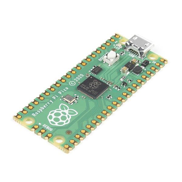
The ESP32 handles everything the Pi would do, with 1/10th the power consumption and no OS overhead. If you need more processing power, look at the ESP32-S3 or the Raspberry Pi Pico W (RP2040) — both are better fits than a full Linux board for this kind of deterministic control application.
What We'd Do Differently
Every project has regrets. Here are ours:
1. Use a separate RFID antenna. The MFRC522's onboard antenna is fine for prototyping, but for production we should've used an external antenna tuned to 13.56MHz. The read range would've doubled.
2. Add a physical emergency stop button. The solenoid valve has a manual override, but when a user's hand got stuck under the spout (yes, it happened), we had to cut power to the whole system. A big red button would've been better.
3. Better water level sensing. The float switch works, but it's prone to jamming. For v2.0, we're testing an ultrasonic sensor (HC-SR04) mounted on the tank lid.
4. More aggressive power management. We could drop the ESP32's clock to 40MHz during idle and use the ULP coprocessor for RFID wake detection. Would save another 20mA in active mode.
Shipping to Production
After three months of field testing, we shipped 50 units to the client in September 2024. Each unit came with:
- Pre-programmed ESP32 with 100 test cards
- 3D-printed mounting brackets and enclosure
- Wiring diagram in Hindi and English
- 5 spare RFID modules and 10 spare solenoid valves
- A SIM card reader for initial credit loading (we programmed a simple Python script that writes credits to cards via a USB RFID reader)
The client handles deployment and maintenance. We provide firmware updates via USB (the ESP32's UART port is accessible through a waterproof panel connector).
Total project timeline: 4 months from initial call to shipping. Budget: $18,000 for design, prototyping, testing, and first production run.
Want to Build Something Similar?
We're sharing the KiCad schematics, Fusion 360 models, and ESP-IDF firmware on GitHub (contact us for the link). If you're working on personalized vending machines for off-grid applications, or if you're a raspberry pi developers looking to switch to lower-power microcontrollers, we're happy to talk.
Our team at DigitalMonk handles firmware development, PCB design, 3D design, and full prototype shipping from our offices in India, the US, and the UK. We specialize in taking hardware from concept to production — no fluff, just working electronics.
Reach out with your requirements. We'll tell you if it's feasible, how much it costs, and how long it takes. No sales pitch, just engineering.
Schematics, diagrams and documents
Credits
chanchaldada
Chanchal Dada is an IoT developer at DigitalMonk, focused on building smart embedded systems using Arduino and ESP32. She specializes in IoT-based automation, smart monitoring solutions, and real-world hardware-software integration for practical applications.
Related products





Leave your feedback...