
Sketch Drive Car

Made by ashokr
About the project
This project aims at controlling a car through a trajectory traced by the user on a screen running windows or android
Items used in this project

Story
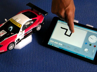
Sketch Drive Car: This is an unique project i have done for Freescale Design Challenge in 2014.I used Freedom Development Board (FRDM-KL25Z) from kinetis Family. Basically there are many ways to control the RC Car but here, we look at the new approach for controlling the car by sketching the route on screen.
I purchased one RC Car from the local store. It has the controls of Right, Left, Forward and Backward. I replaced the existing circuits with Freedom Board(FRDM-KL25Z). Along with Freedom Board i added Bluetooth module (HC-05)and DC motor driver chip LP293DE. Car front lights are connected to the KL25Z port directly. Bluetooth module is connected to KL25Z via UART interface. KL25Z board also has accelerometer which i used to measure the speed of Car. Tri color led's used for status notifications.KL25Z board, LP293DE and HC-05 is powered from 4.5V battery. Battery level is monitor through ADC.The software for this KL25Z is developed using CodeWarrior IDE. I used FreeMASTER for debugging my software.
In the UI side, i developed the windows application and it can run in windows PC/Tablet. It has the controls and draw panels to sketch the route. Also the UI has many features like speedometer , Indicators and battery level etc.
Algorithm:
I designed my own algorithm to convert the 2d drawings into X,Y coordinates with path directions.
Xd= X (i) – X (i-1)
Yd= Y (i) – Y (i-1)
Xd > Xth -> X Direction & Xd < Xth -> -X Direction
Yd > Yth -> Y Direction & Yd < Yth -> -Y Direction
Xth – X Threshold (Sensing value)
How it works? :
Drawing a line on the screen and the car will move forward in the desired direction. The line has two points “Starting” and “Destination” point it decides to where to start and where to end. The distance to travel by the car is decided by scale factor.
This process has 3 stages
1. Routing
2. Decoding
3. Execution
In routing stage, the user is allowed to draw the path on the screen with preferred scale value. Once routing is done the route values are decoded into the X & Y pixel values, which are send to the MCU wirelessly (Bluetooth/ZigBee). In execution stage, the MCU converts the X, Y values into respective a PWM value which drives the DC Motor. The Accelerometer is attached to the car to calculate the acceleration and position of the car thereby helping to track the position of car in GUI screen.
The principle of Sketch Drive Car is conversion of 2D graphics into the form of PWM signals. The Windows application is designed based on Microsoft Paint, with the help of paint the path is drawn into the screen and the X & Y coordinates are stored into the 2D arrays. These values are used to calculate the path direction and motion of the vehicle. The path information is send into the micro controller through Bluetooth. The Micro understands the path information and it drives the Motor according to the changes in path direction in the form of PWM signals.
Error Detection:
The current design does not recognize the curve paths, so Error detection technique is used here to identify the drawn path is valid or not.
Speed Measuring:
The speed of the Car is measured through accelerometer (Approximates values).It detects the motion of vehicle. 8bit fast accessing mode is used in the accelerometer.
Battery Monitoring:
Internal ADC is used to detect the voltage level of battery. Low voltage level can be indicated through LED.
Sketch Drive Car Application:
This application is developed using visual studio along with Measurement Studio tools. In the main tab the large white screen is used for sketching the root/path. Gauges are used to display the speed/motion. Rotatory Knob is used to setup the steering wheel power. Vertical Slide bar is used to setup the engine speed. Push buttons are used to control the lights and drive path of the car. The Setting tab contains Mode and supportive controls.
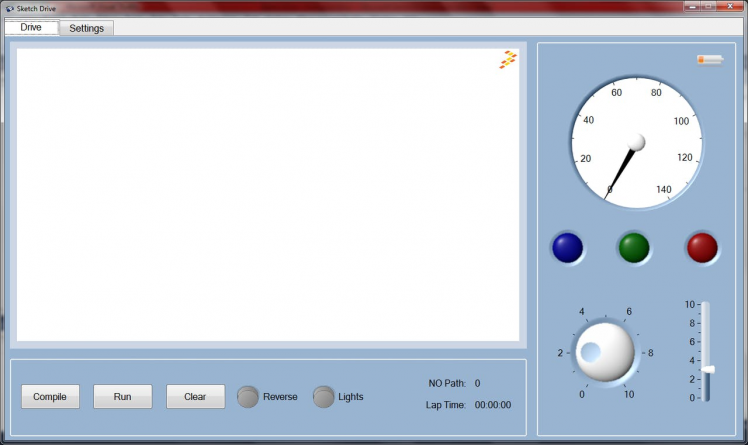
Easy mode:
Using Easy mode user can drive the car as like normal remote control system. Drift and circuit (circular) options are included in this mode. When easy mode is enabled the Sketch driving will be disabled.
Merits:
1. It would be another way to test cars in automotive industries.
2. Sketch Drive Cars can be used in gaming for entertainment (RC car Racing/ Line Follower)
3. Parking the Car in park slots
The working Demo is here
Schematics, diagrams and documents
Code
Credits
Related products


Leave your feedback...