
Sim900a Gsm Module & Arduino

Made by TechnolabElectronics
About the project
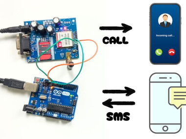
SIM900A GSM Module & Arduino: Sending/Receiving SMS & Making Calls Using AT Commands.
Project info
Difficulty: Moderate
Platforms: Arduino
Estimated time: 1 hour
License: CERN Open Hardware Licence version 1.2 or later (CERN-OHL1.2+)
Items used in this project

Story
If you love DIY electronics, you’ve probably heard about Arduino. It’s a fun and simple way to get into robotics and programming. But did you know you can also use it to send text messages and make phone calls? That’s right! With a little help from a GSM module (like the kind in your cellphone), you can start sending messages and calling from your Arduino project. This article will show you how, step by step. Whether you’re making a smart mailbox, a home alarm system, or just want to learn something new, this guide has got you covered.
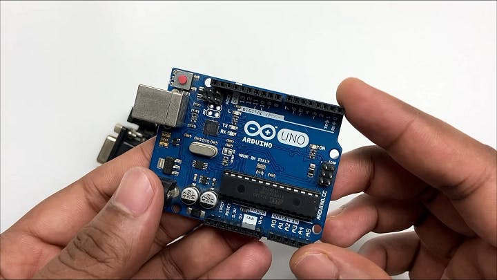
- Arduino Board: Any kind will work, but most people use an Arduino Uno, Mega, or Leonardo.
- GSM Module: SIM900 or SIM800 are good choices.
- SIM Card: A regular SIM card with a call and text plan.
- Connecting Wires: To establish connections between the Arduino and the GSM module.
- Power Supply: Ensure both the Arduino and GSM module are adequately powered.
1 / 2
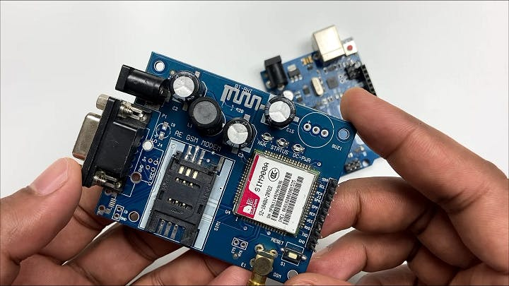
- 2G Module: The SIM900A is a 2G GSM module. This means it’s designed to work primarily on the 2G network. It’s important to highlight this because not all cellular networks support 2G.
- Choosing the Right SIM Card: In India, most telecom companies provide multi-generation services (2G, 3G, 4G, and even 5G). However, not all SIM cards are suitable for the SIM900A module.
- Jio’s Network: Notably, Jio, one of India’s major telecom providers, does not offer 2G services. Jio’s network is based on 4G LTE technology, and as a result, SIM cards from Jio are incompatible with 2G-only modules like the SIM900A.
- Alternative Service Providers: For your Arduino project to work seamlessly with the SIM900A module, you must choose a SIM card from a service provider that still supports 2G networks. In India, this includes providers like Airtel, Vodafone-Idea, and BSNL, which offer 2G services alongside their 3G, 4G, and 5G services.
- Why 2G Matters: The reason why this is crucial is because of the technology used in modules like SIM900A. These modules were designed during a time when 2G was the standard for mobile communications. While technology has since progressed to 3G, 4G, and 5G, these older modules remain limited to 2G.
- Future Considerations: As technology advances and more emphasis is placed on newer networks like 4G and 5G, the availability of 2G networks might decrease. This is an important consideration for long-term projects or products.

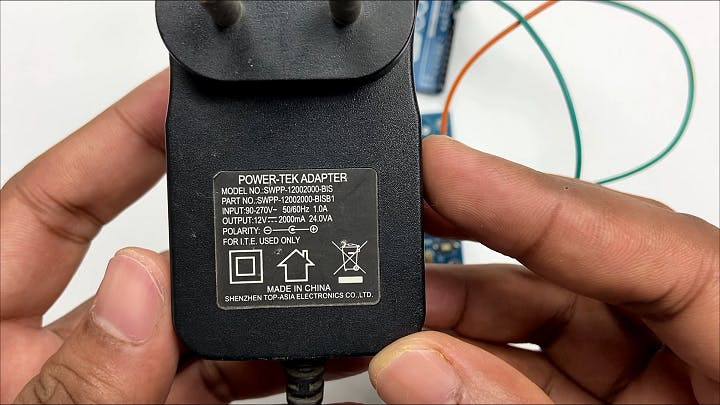
Understanding Power Needs: GSM modules, including the SIM900A, can be sensitive to power supply fluctuations. Their power consumption varies based on network signal strength and the operations they are performing (like sending an SMS or making a call).
SIM900A Specifications: According to its datasheet, the SIM900A module operates efficiently on a 12V, 2A power supply. This specification is critical for the module’s performance and longevity.
Why Correct Voltage and Current are Important:
- Stability: GSM modules transmit and receive data, which requires bursts of power, especially in areas with poor network reception. An inadequate power supply can lead to module instability or failure to perform tasks.
- Safety: Using the wrong power specifications not only risks the module’s functionality but also can damage the module or connected components.
Checking the Datasheet: Always consult the datasheet of the GSM module for precise power requirements. The datasheet is the most reliable source for technical specifications and will provide guidance on the optimal operating conditions.
Power Supply Options:
- Dedicated Power Source: Given the power requirements, a dedicated power supply that can deliver a stable 12V and 2A is recommended for the SIM900A.
- Avoiding USB Power: While some smaller modules can be powered via USB, the SIM900A’s requirements exceed what standard USB ports can provide. Therefore, relying on USB for power is not advisable.
Monitoring Power Delivery: In your project, include a means to monitor the power supply to the GSM module. This can be through voltage regulators or by using Arduino to detect and respond to power fluctuations.
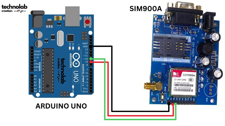
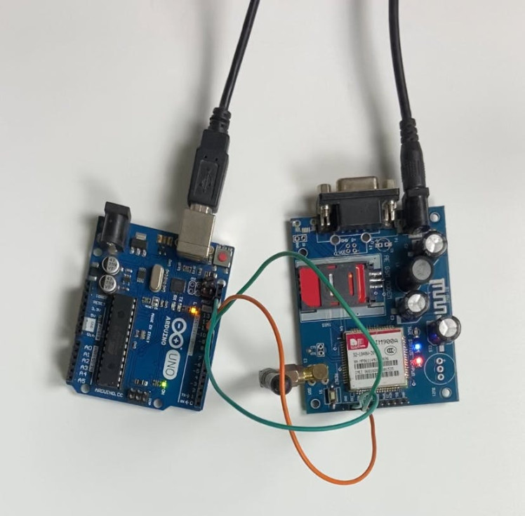
Make the connections as per the below connection diagram.
AT Commands, short for Attention Commands, are a set of instructions used to control modems. Originating in the early days of computer telecommunications, these commands provide a standard language for modems and other communication devices to interpret and execute commands. Here’s a general overview:
1.History: AT Commands were initially developed for the Hayes Smartmodem 300 in the early 1980s. They have since become a standard for controlling modems.
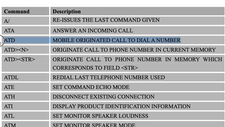
2.Syntax: The commands typically start with the prefix “AT” (which stands for Attention) to get the modem’s attention. Following this prefix are various commands that instruct the modem what to do. For example, “ATD” followed by a phone number would instruct the modem to dial that number.
Types of Commands:
Basic Commands: These are general commands, such as “ATD” for dial, “ATA” for answer, and “ATH” for hang up.
Extended Commands: These are more specific and can control various modem parameters or return information about the modem’s status.
Manufacturer-Specific Commands: Different modem manufacturers may implement additional custom commands for advanced features specific to their products.
4.Uses: While originally designed for dial-up modems, AT commands have found uses in a variety of other telecommunications devices. For instance, they are widely used in GSM and GPRS modems and devices for sending SMS messages, making calls, or accessing internet services.
5.Execution: The commands can be executed via a serial interface (RS-232), over a network, or even within a system (like a computer or a mobile device) depending on the device and its capabilities.
6.Modern Relevance: Even though dial-up modems have largely become obsolete with the advent of broadband internet, AT commands are still relevant in areas like IoT (Internet of Things), where they are used to control and configure GSM/GPRS modules and other telecommunication devices.
NextPCB: Your One-Stop Solution for PCB Manufacturing and Assembly.
1 / 2
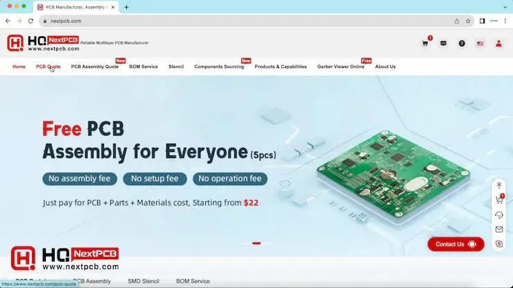
This project is successfully completed because of the help and support from NextPCB -Reliable Multilayer PCB Manufacturer. NextPCB is one of the most experienced PCB manufacturers in Global, has specialized in the PCB and assembly industry for over 15 years.
- Sign up/login to get exclusive $30 coupon:
- Enjoy free PCB assembly for 5 boards:
- HQDFM free online PCB Gerber viewer:
Unmatched Reliability and Quality
NextPCB prides itself on offering high-reliability PCB solutions. With over 15 years of in-house fabrication expertise, they guarantee 100% quality on their products, promising to remake them free of charge if any issues arise. Their commitment to quality is reflected in their impressive 99.6% on-time delivery rate, ensuring that your projects adhere to the stipulated timelines without any hitches.
Comprehensive Services
PCB Manufacturing
NextPCB specializes in manufacturing a wide variety of PCBs, including:
- Ceramic PCB
- Metal Core PCB
- Aluminum PCB
- LED PCB
- Flexible PCB
- Rigid-flex PCB
- Thick Copper PCB
- High TG PCB
- High-frequency PCB
- HDI PCB
Their manufacturing process utilizes high-end materials and equipment sourced globally, including Taiwanese electroplating lines and German flying probe testers, ensuring the production of durable and efficient PCBs.
Free PCB Assembly Services
In a bid to support engineers and enthusiasts in their endeavors, NextPCB offers free PCB assembly services, allowing individuals and businesses to experience reliable PCB assembly from NextPCB without any cost. This initiative stands as a testament to NextPCB's commitment to fostering innovation and supporting the PCB community.

CODE
Click here to download the code.
#include <SoftwareSerial.h>

int i;
SoftwareSerial mySerial(9, 10);

void setup()
{
  mySerial.begin(9600);   // Setting the baud rate of GSM Module
  Serial.begin(9600);    // Setting the baud rate of Serial Monitor (Arduino)
  delay(100);
}


void loop()
{
  if (Serial.available()>0)
   switch(Serial.read())
  {
    case 's':
     Serial.println("Sending text Message through GSM Module");
     mySerial.println("AT+CMGF=1");    //Sets the GSM Module in Text Mode
     delay(1000);  // Delay of 1 second
     mySerial.println("AT+CMGS="+918543053029"r"); // Replace x with mobile number
     delay(1000);
     mySerial.println("Hello from GSM Module");// The SMS text you want to send
     delay(100);
     mySerial.println((char)26);// ASCII code of CTRL+Z for saying the end of sms to  the module
      delay(1000);
      break;

     case 'r':
      mySerial.println("AT+CNMI=2,2,0,0,0"); // AT Command to receive a live SMS
      delay(1000);
      break;

      case 'c':
      if(i==0)//i variable to ensure that only one call request will be sent by gsm during pressing and holding the pushbutton;
        {
          Serial.println("Calling through GSM  Module");
          delay(1000);
          mySerial.println("ATD8543053029;"); // ATDxxxxxxxxxx; semicolon should be at the last ;AT command that follows UART protocol;
          Serial.println("Calling 8543053029");
          delay(1000);
          i++;
         }
   i=0;

      break;
  }

 if (mySerial.available()>0)
   Serial.write(mySerial.read());
}
This Arduino code is designed to interface with a GSM module using AT commands for sending SMS messages, receiving live SMS, and making phone calls. The code uses the SoftwareSerial library to create a serial communication interface with the GSM module. Let’s break down the code section by section:
#include <SoftwareSerial.h>

int i;
SoftwareSerial mySerial(9, 10);- #include <SoftwareSerial.h>: Includes the SoftwareSerial library, which allows for serial communication on digital pins of the Arduino.
- int i;: A variable ‘i’ used later in the code.
- SoftwareSerial mySerial(9, 10);: Creates a new SoftwareSerial object named mySerial using digital pins 9 and 10 of the Arduino for RX and TX, respectively.
The setup Function
void setup()
{
  mySerial.begin(9600);   // Setting the baud rate of 4G LTE Module
  Serial.begin(9600);    // Setting the baud rate of Serial Monitor (Arduino)
  delay(100);
}
This function initializes the serial communication.
- mySerial.begin(9600);: Starts serial communication with the GSM module at 9600 baud.
- Serial.begin(9600);: Starts serial communication with the computer (Serial Monitor) at 9600 baud.
- delay(100);: A short delay to ensure that the communications are set up properly.
The loop Function
This function continuously runs, checking for input from the Serial Monitor and responding accordingly.
Sending SMS (‘s’ command)
void loop()
{
  if (Serial.available()>0)
   switch(Serial.read())
  {
    case 's':
     Serial.println("Sending text Message through 4G LTE Module");
     mySerial.println("AT+CMGF=1");    //Sets the 4G Module in Text Mode
     delay(1000);  // Delay of 1 second
     mySerial.println("AT+CMGS="+91XXXXXXXXXX"r"); // Replace x with mobile number
     delay(1000);
     mySerial.println("Hello from 4G LTE Module");// The SMS text you want to send
     delay(100);
     mySerial.println((char)26);// ASCII code of CTRL+Z for saying the end of sms to  the module
      delay(1000);
      break;
Checks if there is data available to read from the Serial Monitor.
If the character ‘s’ is received, it triggers the SMS sending sequence:
- mySerial.println(“AT+CMGF=1”);: Sets the GSM module to text mode.
- mySerial.println(“AT+CMGS=”+918543053029”r”);: Sets the number to send the SMS to. Replace the number with the desired recipient’s number.
- mySerial.println(“Hello from GSM Module”);: The message to be sent.
- mySerial.println((char)26);: Sends the ASCII code of Ctrl+Z to indicate the end of the message.
Receiving SMS (‘r’ command)
case 'r':
      mySerial.println("AT+CNMI=2,2,0,0,0"); // AT Command to receive a live SMS
      delay(1000);
      break;
If the character ‘r’ is received, it configures the GSM module to notify when a new SMS is received.
Making a Call (‘c’ command)
case 'c':
      if(i==0)//i variable to ensure that only one call request will be sent by gsm during pressing and holding the pushbutton;
        {
          Serial.println("Calling through 4G LTE Module");
          delay(1000);
          mySerial.println("ATD8543053029;"); // ATDxxxxxxxxxx; semicolon should be at the last ;AT command that follows UART protocol;
          Serial.println("Calling 8543053029");
          delay(1000);
          i++;
         }
   i=0;

      break;
If the character ‘c’ is received, it initiates a phone call:
- mySerial.println(“ATD8543053029;”);: Dial the number (replace with the desired number).
- I is used to ensure only one call is made per button press or command.
Reading from GSM Module
if (mySerial.available()>0)
Serial.write(mySerial.read());- This part reads any incoming data from the GSM module and forwards it to the Serial Monitor, allowing you to see responses from the GSM module or incoming SMS messages.
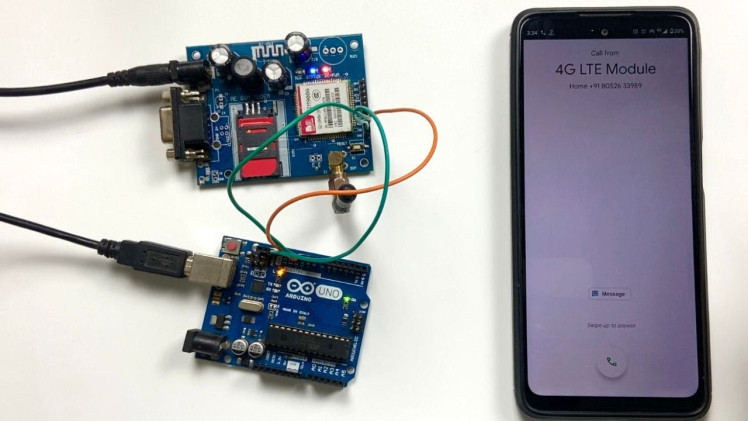
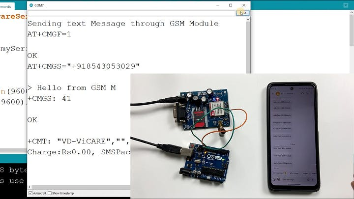
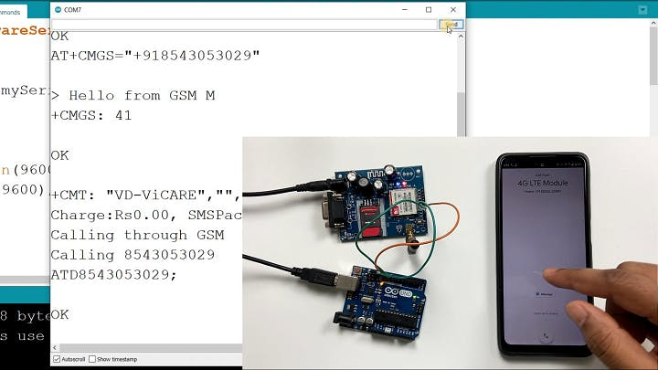
Testing It Out.
- Upload Your Code: Put your Arduino code onto the board.
- Try Sending Texts and Making Calls: Use the Serial Monitor on your computer to send commands for texts and calls.
1 / 2
Conclusion.
Combining Arduino with a GSM module is a fantastic way to add communication to your projects. You can make things like a gadget that tells you when you have mail, or a home security system that calls you if something’s wrong. It’s not just fun – you’ll learn a lot about electronics and programming too. Remember, this is just the beginning. There’s so much more you can do with Arduino and GSM!
Schematics, diagrams and documents
Credits
Related products


Leave your feedback...