
Items used in this project
Hardware components

View all
Software apps and online services
Hand tools and fabrication machines
Story
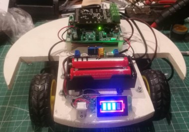
I want to design an OpenSource/OpenHardware robot for indoor investigation.
This robot will has 3 wheels. Two wheels are with motors, third is free for rotation.
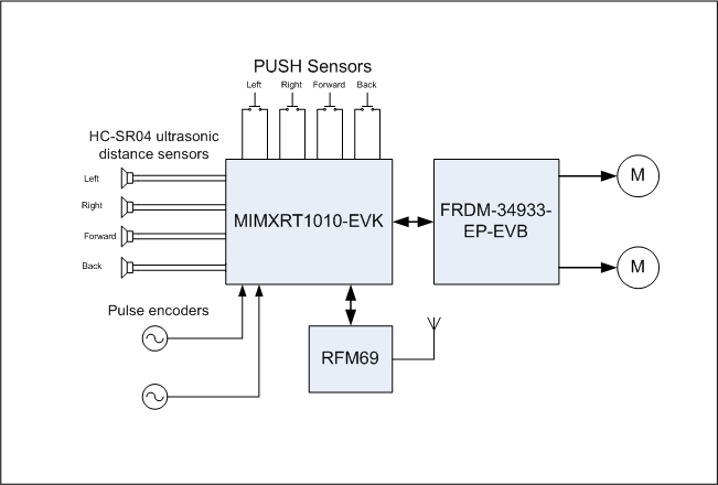
For measure a distance I shall use 4 ultrasonic distance sensors HC-SR04. This sensors will control all sides of robot: left, right, forward, back. For determine collision I shall use simple push sensors for all sides too. For accurate measure speed and distance will use counter encoders with special measurement wheels.
In movement all distances sensors will measure distances to any objects. In case the robot is moving by unknown environment the data about distance will be used for build virtual map. In case the robot is moving by known space the data will be used for navigation and build path by Lee algorithm.
For communication with external eqipment I shall use RFM69 module. The Mavlink and ROS protocols will be supported. The robot will be as ROS remote device.
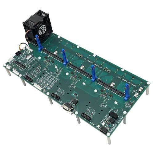
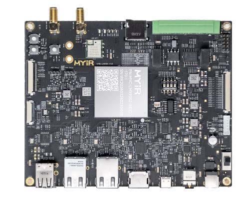
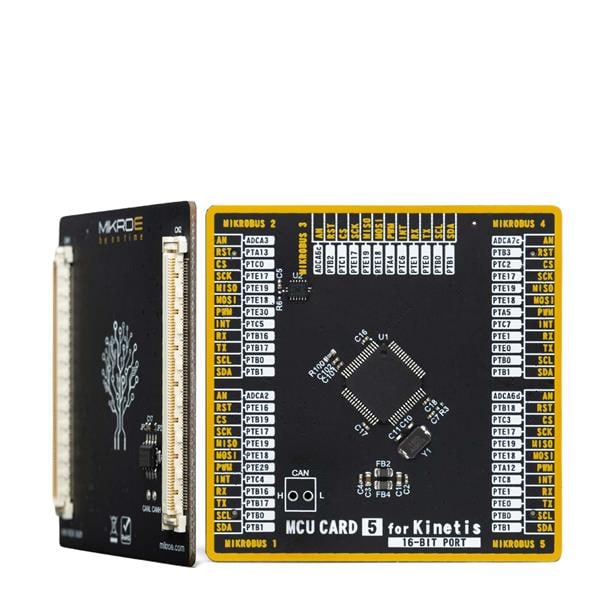
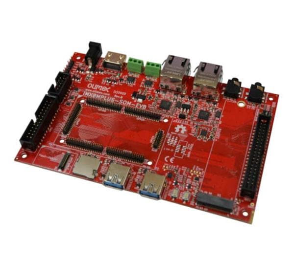
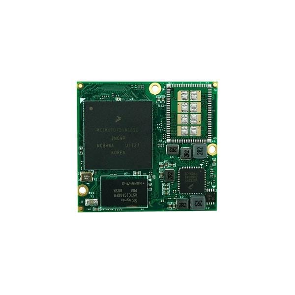
Main controller is Development Kit MIMXRT1010-EVK from NXP, motor's control board is FRDM-34933-EP-EVB. Thanks a lot of NXP by these boards.
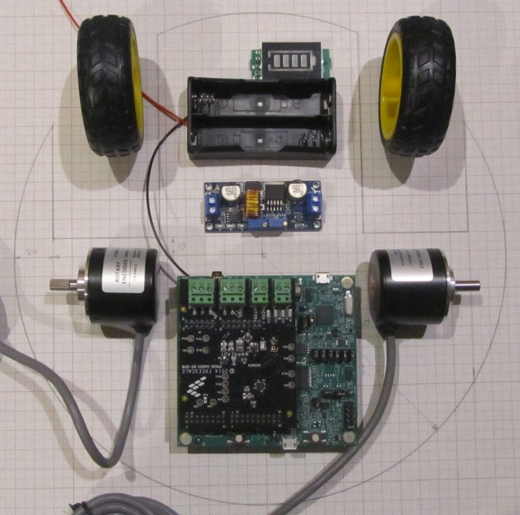
See structure of the robot.
Plan of work:
1. Design a frame, motor's brackets. Assembly a frame with motors. - Done
2. First movement. Do it moveable by programm. - Done
3. Design brackets for counter encoders. Assembly with encoders. Do working measure speed, direction and distance.
4. Add to each side ultrasonic distance sensors HC-SR04. Do working measure distances.
5. Add push sensors to each side.
6. Add RFM69 module. Do working communication with external equipment.
7. Design an algo for navigation and path planning.
8. Do working Mavlink/ROS data transfer.
9. Indoor tests.
Design a frame, motor's brackets. Assembly a frame with motors and wheels.
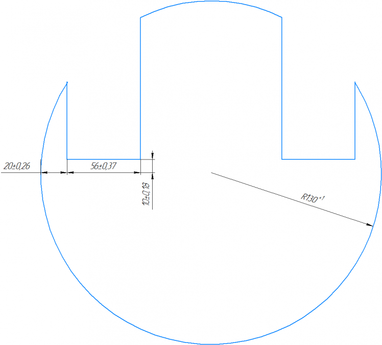
For this project I used 6 layers (10mm width) plywood. It looks as circle with holes. See draft (mm units).
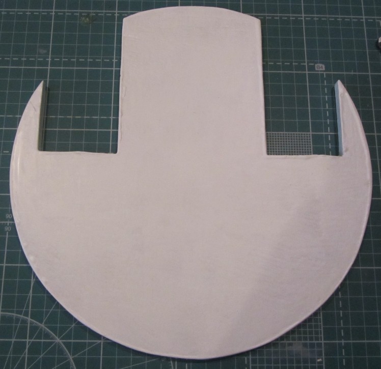
This cutted frame was covered 2 layers of white paint of wood.
Motors are from there https://aliexpress.ru/item/32835628707.html
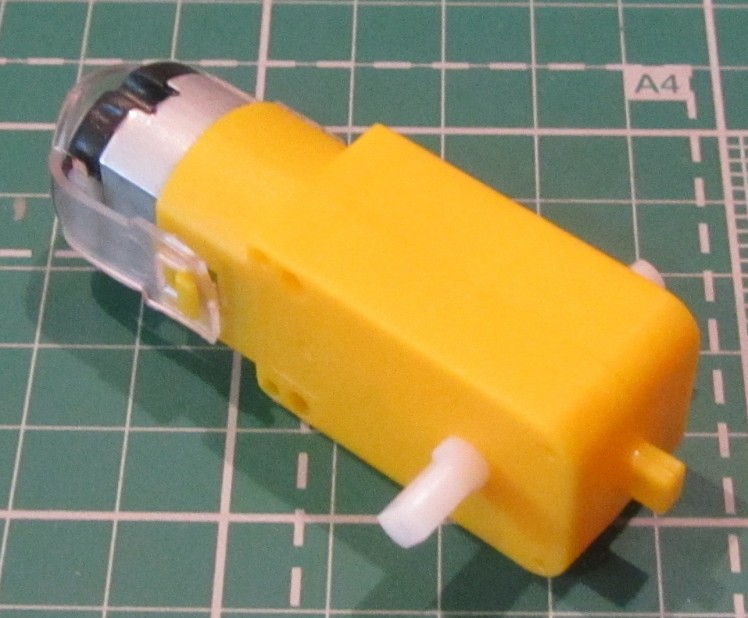
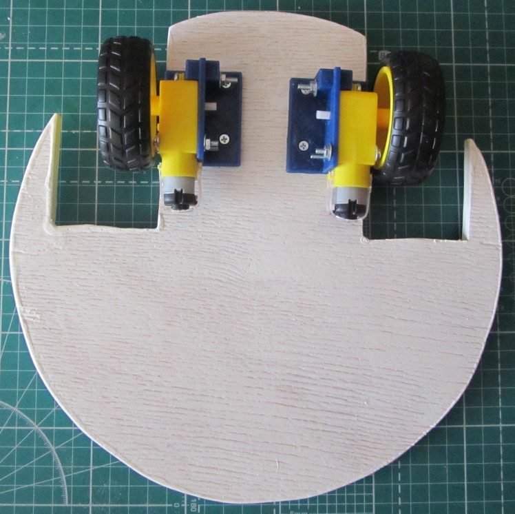
Motors will be placed on the bottom of this frame. 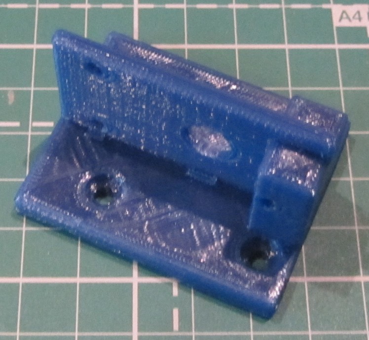
For do it. I designed universal bracket (left/right side).
3D printers may slightly change dimensions of model. When brackets printed set its to bottom of the frame as on image and mark centers of holes. Distance between brackets and corner is 25mm.
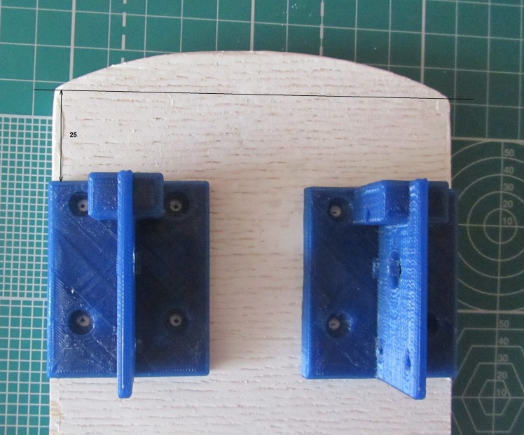
Drill 8 holes with 3.2 - 3.5mm diameter.
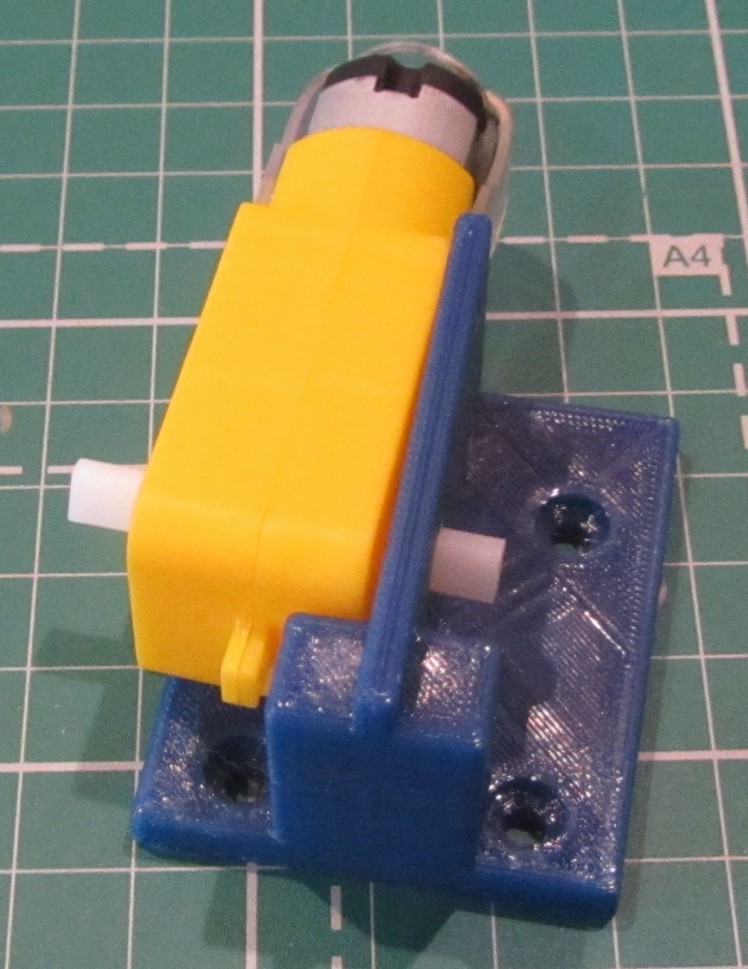
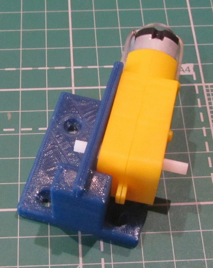
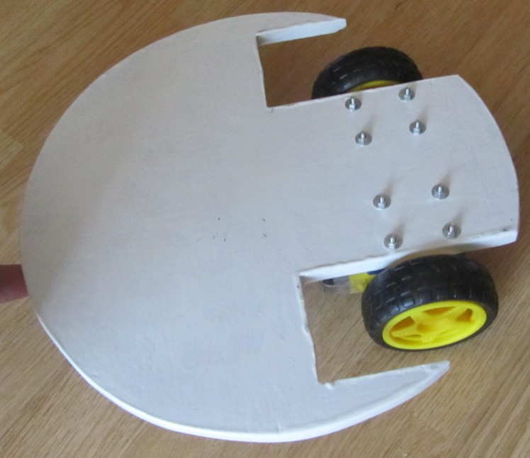
For mount brackets use 8 M3-20...25mm screws with hidden head and spacers on top side of the frame.

For mount motors use 6 M3-25..30mm screws and spacers on some places.
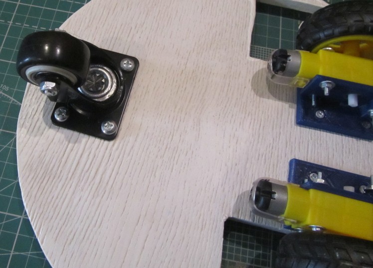
When motors with wheels installed we may measure distance between ground and bottom of this frame. We need know this information for bought free rotation wheel. In my case this distance is 49..50mm.
I found in local store simple free rotation wheel.

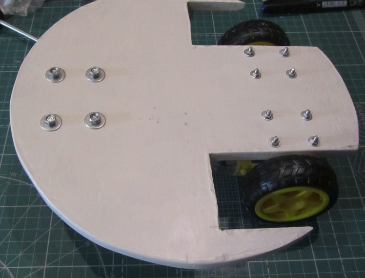
Marked centers of mount holes, drilled holes and mount. In my case mount holes diameter is 5.5mm. I used 4 pcs of M5x16mm screws.
Well, frame with motors and wheels is ready for electronic and programming stage.
First movement. Doing moveable by programm.
The base of robot ready for next step. It is do it moveable.
The signals for control motors for the FRDM-34933EP-EVB are on the J56 of the MIMXRT1010-EVK. But main problem is that all signals of FLEXPWM1 disconnected by default.
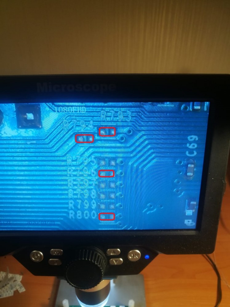
Need solder additional 4 pcs of 0402 SMD resistors zero value: R793, R794, R796, R800. These resistors are on the bottom side.
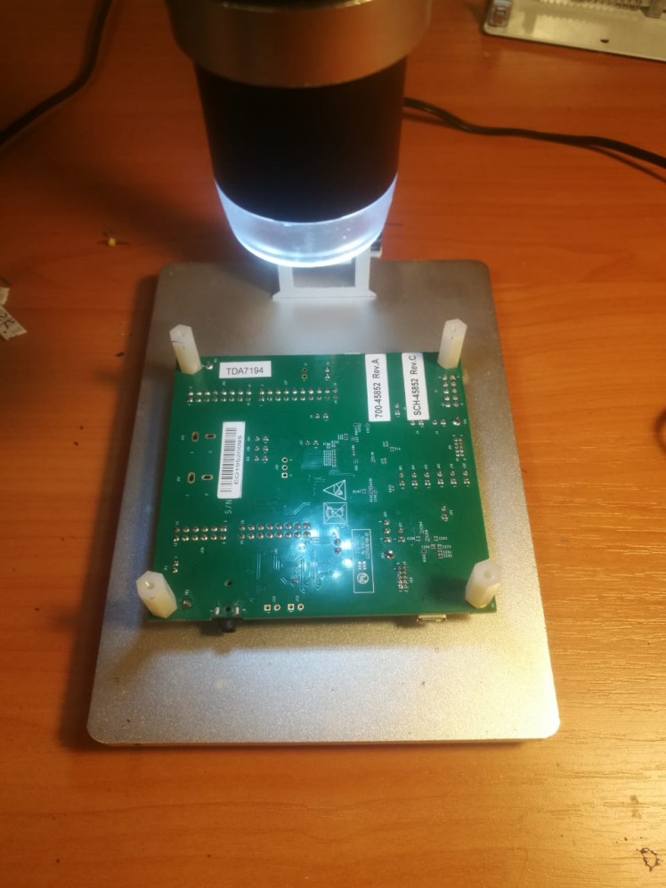
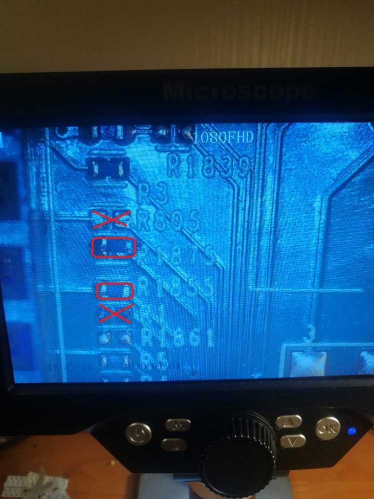
On the top side need move resitors R1 to R1855 and R805 to R1875
Now the MIMXRT1010-EVK is ready for control motors.
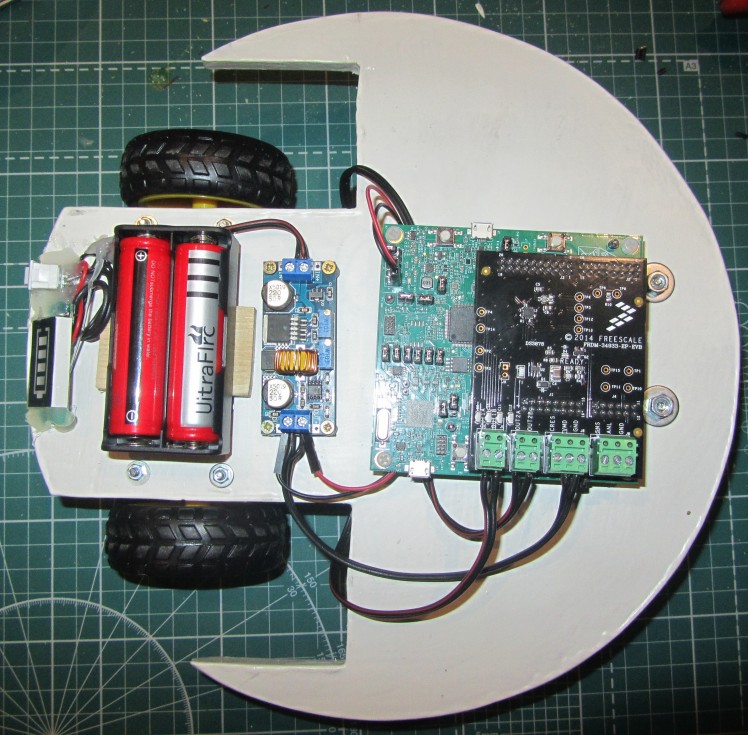
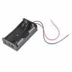
Mount battery holder, DC-DC and MIMXRT1010-EVK by screw.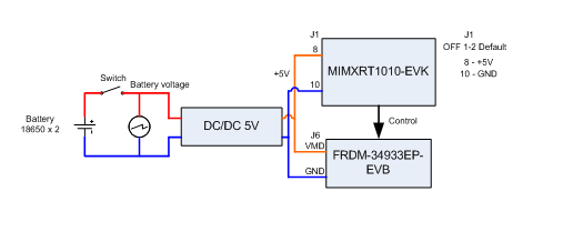
The board FRDM-34933EP-EVB can't control high voltage motors. In this case we use special DC-DC with +5V 2..5A output for supply both boards and motors.
For the MIMXRT1010-EVK board before supply from external source need remove default connection on J1 1-2pins and connect +5 to 8 pin of J1 and GND to 10 pin of J1. Power for motors will be connected to J6 of the FRDM-34933EP-EVB +5V to VMD, GND to GND.
The left motor connected to OUT1 channel, the right motor connected to OUT2 channel.
Use simple project for test woring state. This stage is done.

Schematics, diagrams and documents
CAD, enclosures and custom parts
Code
Credits

Pitman75
I am professional electrical engineer with strong embedded development experience. I search for an interesting and complex long-term project. I can do project from start (design schematic) to finish (production). I have very well-equipped professional engineering lab with everything needed to create working prototypes—from logic analyzers to 3D printer and CNC mill. EDUCATION www.tusur.ru Tomsk State University of Control Systems and Radioelectronics Master of Electrical Engineering
Related products


Leave your feedback...