
Psoc4 : Bootloader, Timer, Interrupts, Sleep, I/o, Lcd & Imo

Made by electrouser805 / Communication
About the project
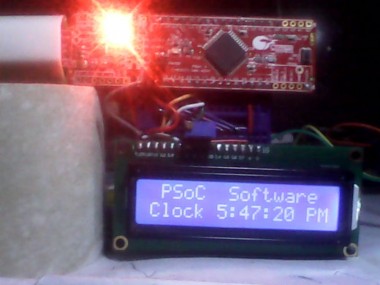
A Software Only Clock demonstrating Timer, Interrupts, Sleep Mode, Power Over I/O, LCD Driver, Bootloader, IMO modification for PSoC 4.
Project info
Difficulty: Moderate
Platforms: Cypress
Estimated time: 1 hour
License: GNU General Public License, version 3 or later (GPL3+)
Items used in this project
Hardware components

Story
This project is not only about how to make a Clock with PSoC 4 but also how to use some of the features of PSoC 4, how to program in PSoC creator and some info about this kit !
For this project , you will need :
1. PSoC 4 CY8CKIT 049 4200 kit
2. Mini Breadboard
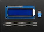
3. HT44780 LCD 16x02 display
4. Male Pin Headers
5. Breadboard Jumper wires
6. 10k Multi-Trim pot
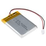
7. 5 Volt Battery Pack (optional)
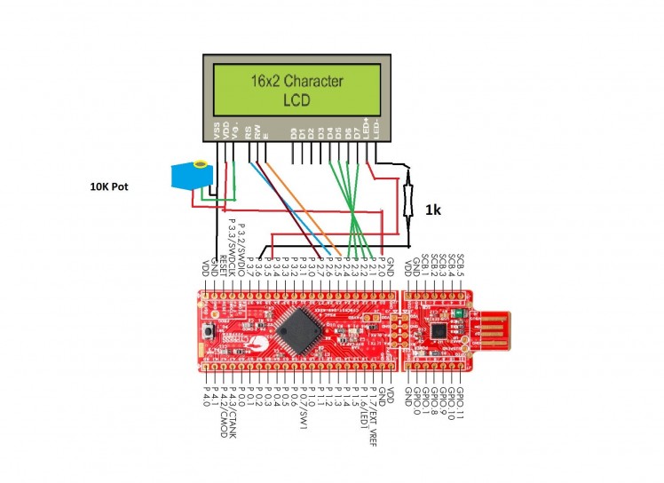
Solder the male headers on PSoC 4 kit's lower side ( from Ground, Pins 2.0, 2.1, 2.2 .....upto 3.7). Also, solder male headers on HT44780 16x2 LCD (from "Vss" to "E" and "D4" to "K" .
Now, Plug them into the mini breadboard, connect with breadboard wires as follows :
PSoC-049 Kit ---- LCD Display------10k Pot
V0 Mid Pin (sweep)
Gnd Vss Right Pin
Pin 2.0 Vdd Left Pin
Pin 2.1 D4
Pin 2.2 D5
Pin 2.3 D6
Pin 2.4 D7
Pin 2.5 E
Pin 2.6 RS
Pin 2.7 RW
Pin 3.5 A
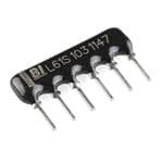
Pin 3.6 K (add 1K resistor between pin 3.6 and K)
Now, Run "PSoC Creator", Open: File > New > Project > Empty PSoC 4 design > OK
Put your Desired "Name" for project and "Location" on your PC.
TopDesign.cysch window will appear in PSoC Creator !
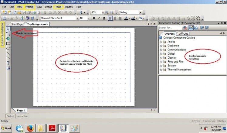
Components Catalog holds the peripherals (I/O, UART, PWM, Timer, ADC of MCU), UBD based units (AND, OR, Register....) Programmable Analog (OpAmp, Mux ...).
Drag and Drop them to add to TopDesign.cysch window, double click to Configure them and Use Wire to interconnect them (Red Circles in Picture above)
Workspace Explorer, View, Project, Tools are the most important 4 Menus you will need frequently. (Yellow boxed in Picture above)
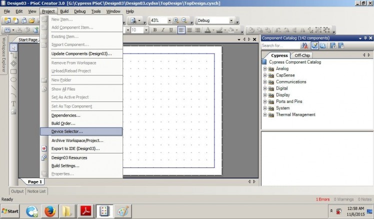
Project > Device Selector > CY8C4245AXI-483 is the PSoC 4 Chip used in this Kit ! If not selected by default, you must select this device from here ! (Picture below)
 1 / 2
1 / 2
Project > Bulid Settings > (Inside Code Generation Box) Application Type : Bootloadable is must for this kit, If not selected by default, you must select this option from here ! (Picture below)
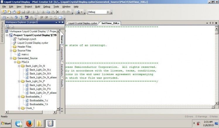
From Workspace Explorer tab you can access 3 most important windows of PSoC Creator :
1. TopDesign.cysch ( internal components , schematics, initial configuration )
2. <project name>.cydwr ( pin routing to Real I/O, Oscillator setting, Interrupts )
A finished project's TopDesign.cysch will look like this : (picture below)
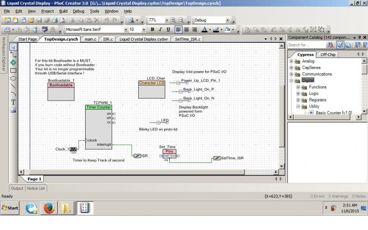
Watch Out : Bootloader for this Kit !
This is very important, if you upload code to your PSoC 4 CY8CKIT 049 4200 kit without the "Bootloadable" component in the TopDesign.cysch window and don't add the the UART_bootloader.hex file in the component , you kit is (almost) good as dead.
Unless you have another spare PSoC4-049 kit or Miniprog3 Programmer to burn bootloader into the bricked kit.
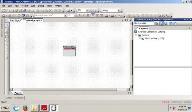
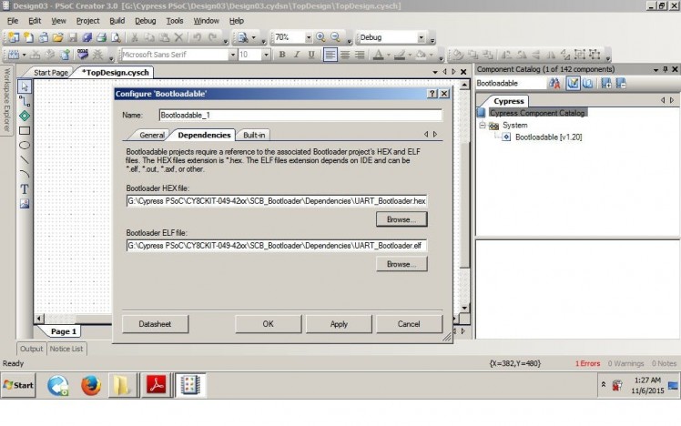
Adding a Bootloadable component and linking the bootloader is the first and most important step, every time you do a new project with this kit !
(See the pictures above)
What is API in PSoC ?
From Google :
API, an abbreviation of application program interface, is a set of routines, protocols, and tools for building software applications. The API specifies how software components should interact and APIs are used when programming graphical user interface (GUI) components.
_ Vangie Beal.
In other words, these are functions like Arduino's digitalWrite (pin,state), analogRead(pin) to do something. For example, if a pin component is named "LED" (because a LED is connected to the physical pin associated with this component pin), then "LED_Write (1)" API will make the pin "High". If you rename the pin component "SAM", then the API will be "SAM_Write (1)" .
API Writing Style: the underscore thing !
When you add a component, rename it, then build file - APIs are generated with component name prefix, then underscore, then the function name part for that component !
For a Character LCD Display component named " LCD_Char_1 ", APIs will be like this :
LCD_Char_1_Start(); // Initializes the display
LCD_Char_1_DisplayOn(); // turns on the display
LCD_Char_1_Position(0,0); // set cursor at 0 row, 0 column
Now, if your LCD component was named " MyLCD ", then APIs will be like this
MyLCD_Start(); // Initializes the display
MyLCD_DisplayOn(); // turns on the display
MyLCD_Position(0,0); // set cursor at 0 row, 0 column
Well, in PSoC we have APIs associated for every component. Details for the APIs can be found in components Datasheets !
Datasheets: What the heck ?
Yes ! PSoC has datasheets (in pdf) for each and every of these internal components !
There is more, AN- the application notes for GPIO, Interrupts, Touch, User Manuals for these kits, PSoC Creator, datasheet for the real chips ( like CY8C4245AXI-483 ), datasheets for the Architectures (like ARM).
The good thing is, there are examples but the bad thing is, you have to find it !
By double clicking on the component. configure window for that component will appear, with datasheet on the bottom left corner (picture below) , click on it to open the datasheet !
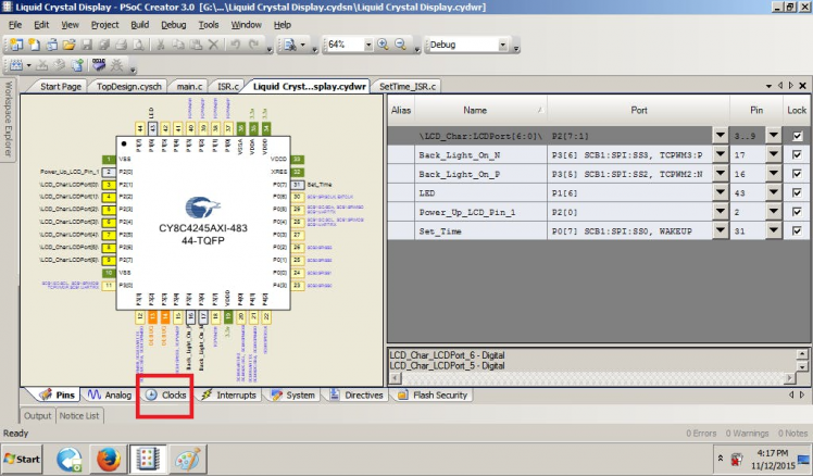
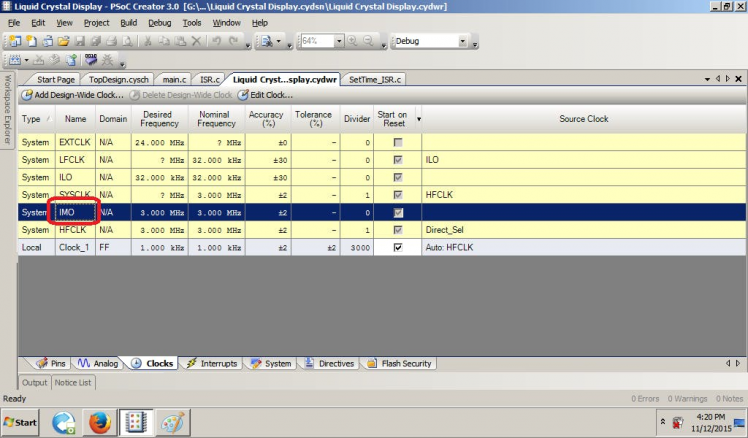
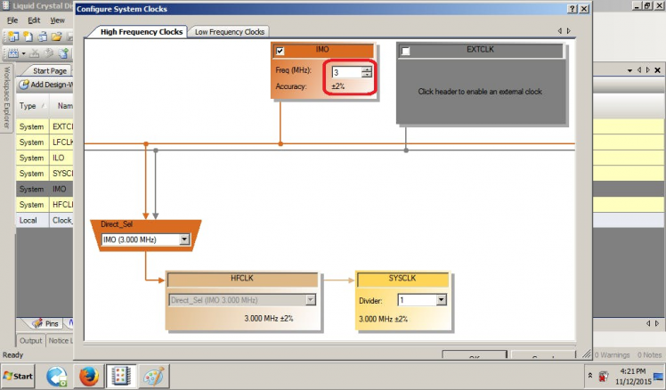
IMO (Internal Main Oscillator) : Easy clock speed adjustment as needed !
This kit has no external crystal oscillator, but there are several internal clock options. Internal Main Oscillator (IMO) can oscillate at any frequency between 3 MHz to 48 MHz. Lower frequency will result lower power consumption (in most cases).
To modify IMO, go to <project name>,cydwr window, there is a tab below named "clocks", click here to enter clock settings page, now double click on IMO to get into the configure system clocks window. Now type 3 in the IMO freq box for 3 MHz clock , then OK. You are done here !
See the images below (with red boxed) for this part !
Pins : connected where?
Since PSoC 4 has flexible routing for most of the functions, you need to understand the difference between Pin Components and Actual Physical Pins of the chip !
Pin Component is an abstract thing (!) for a pin's behavior where you name the pin (APIs will be generated with that name in prefix), configure the pin ( Digital Input/Output/Both or Analog if used as ADC/OpAmp/Comparator/Mux I/O, set Drive Mode - Pull Up/Down/Strong and many other settings). You can also connect additional off chip components from components catalog to that pin which is purely for documentation purpose.
This part is done in TopDesign.cysch window of PSoC Creator by dragging a Pin Component and double clicking on it to open configure window of that Pin Component
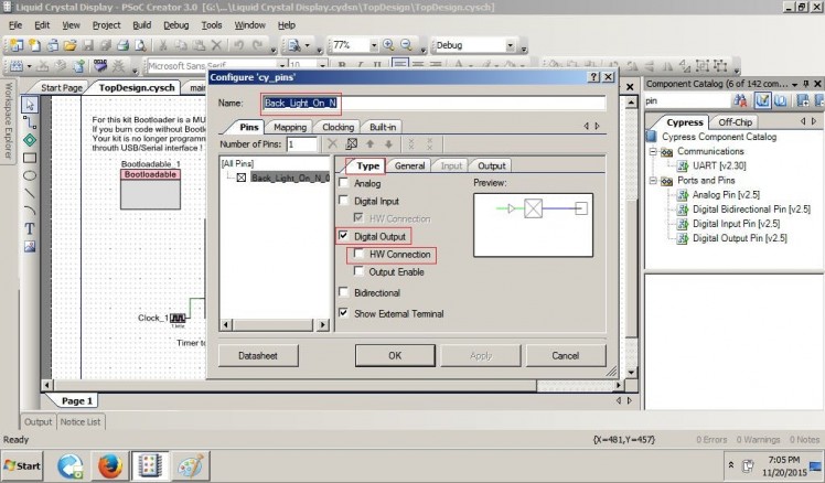
In the Type tab (picture above) of Pin Component Configure window, where it is configured as Digital Output (checked) because Digital Output Pin was dragged from the component catalog.
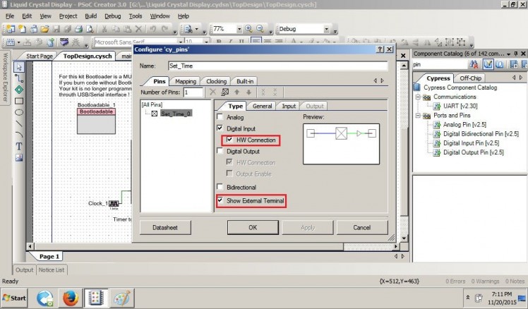
One very important parameter here is HW Connection, which should be unchecked if a pin is controlled from software/c code but if you are going to control a pin state from hardware ( like the switch SW1 of this prototyping kit connected to physical pin P 0.7 ) then HW Connection, should be checked. (picture below)
In the General Tab drive mode for the pin is configured, Strong drive means a physical pin that is associated with this pin component will be able to both Source (when High) and Sink (when Low) few mA of current (safely 8mA, absolute max 25mA) to drive a load (LED,Transistor,Low power digital ICs).
Pull Up/Down drives will make pin high/low through an internal resistor (around 5.6k), which is useful for making a Physical Input's idle state.
So, how do we associate these this pin components to physical real metal pins coming out of the chip ? In the <project name>.cydwr window's Pins tab, this job is done ! See the table on right side with Name column, where the pin components names have appeared ? Drag a component's name to a pin of the chip's pinout shown on left and drop, done ! (see picture below)
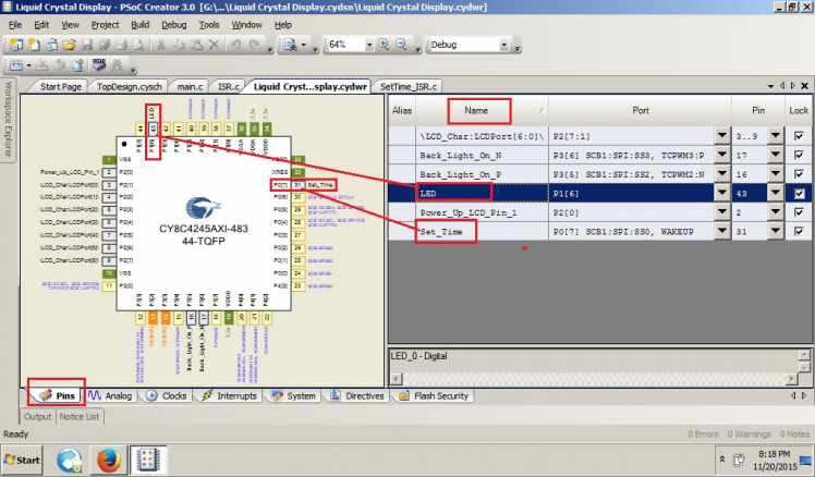
For this project, on kit Blue LED which is connected to physical pin P 1.6 and momentary contact switch SW1 which is connected to physical pin P 0.7 are associated with Pin Components named LED and Set_Time.
Timer : also counter, PWM
PWM on PSoC4 : Controlling Frequency and Duty
Check these tutorials of mine and Alan Hawse for PSoC4 to understand TCPWM
Interrupt and ISR Components : another c file !
volatile variables are used for ISR, I will explain about the other c file maybe some other time. There are 2 ways to deal interrupts in PSoC Creator. You may read this to understand.
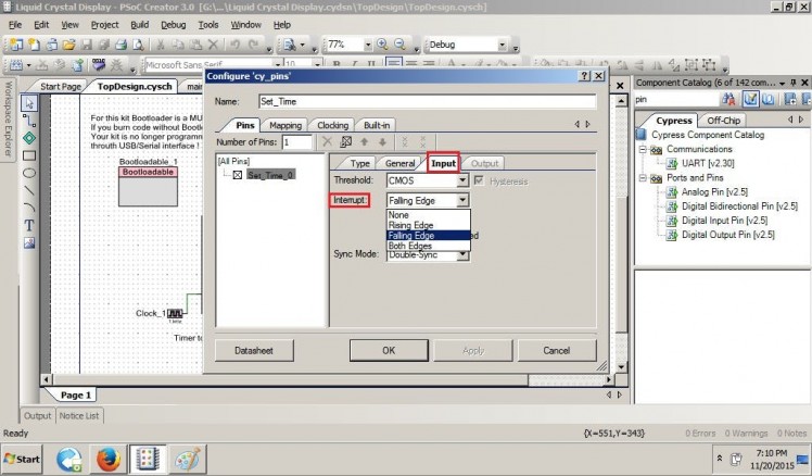 Configuring Pin Input (Button Press) for interrupt on Falling Edge
Writing the The C code
In PSoC Creator, Configuration of different peripherals are done with Graphical IDE which is usually done with other Microcontrollers the hard way. (by Setting/Clearing Registers manually).
In the C code, _Start() APIs initiates the peripherals, timer interrups every second and updates time. In between every second, the ARM M0 Sleeps. User button press also generate interrupts to adjust time as needed.
LCD Vdd and Back light are powered from GPIO pins, so it is possible to turn them off from code if needed.
In PSoC, it is possible to design hardware only solution without writing any C code at all.
Check out this Water Cannon Wiper Bot Project without any C code.
Sleep Modes
Form AN86233 PSoC 4 has -
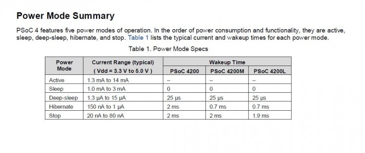 Sleep Modes
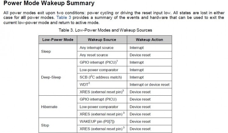 Wake up From Sleep
Here, we have used CySysPmSleep() API to go into Sleep Mode
, The Time keeping Timer interrupts every second, CPU wakes up, update the time and then go back to sleep again. It's like sleeping 900+ mS of 1 second for every second.
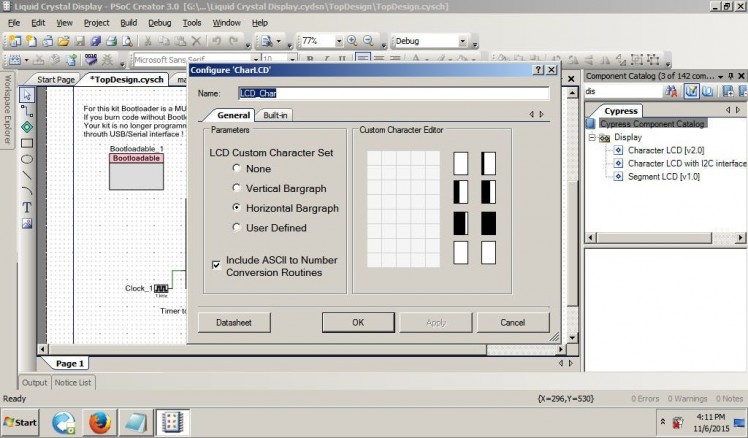
LCD Driver : contagious pins of same port !
PSoC 4's LCD driver module requires 7 contagious pins of same port .Like P0.0 to P0.6 or P1.1 to P1.7. Can't mix pins of different Ports here, kinda failure (no PSoC magic), see LCD datasheet in PSoC Creator.
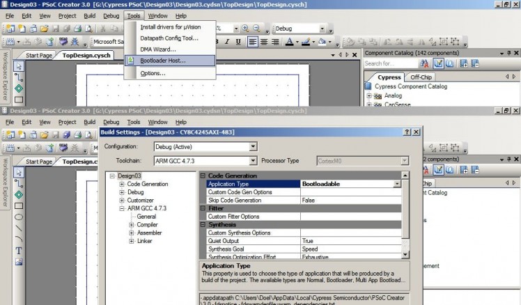
Program the kit : Bootloader Host !
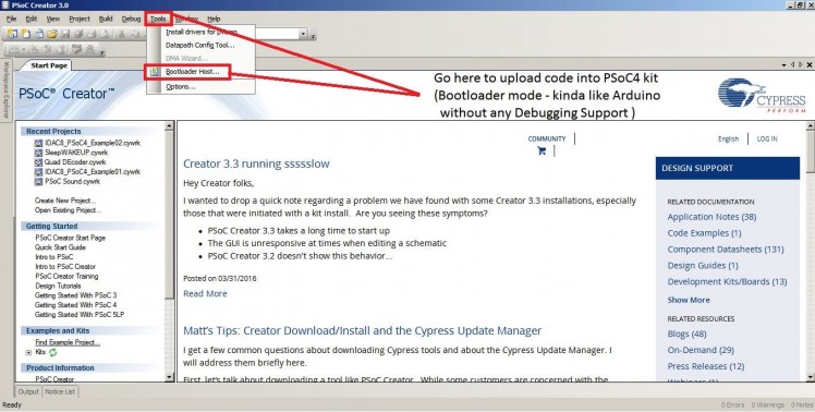 Programming the Kit
Click on Tools>Bootloader Host
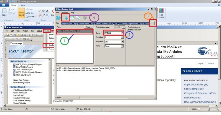
1. Select USB-Serial Com Port for PSoC kit
2. Set Baud Rate 115200
3. Now find the your_project_name.cyacd (here Liquid Crystal Display.cyacd) in PSoC Creator Installed directory of your computer
like this -
G:Cypress PSoCLiquid Crystal DisplayLiquid Crystal Display.cydsnCortexM0ARM_GCC_473DebugLiquid Crystal Display.cyacd
4. Click Program button (Blue arrow)
Note
PSoC Creator 3.0 is used to program the kit ! Later version of PSoC Creator has issues with showing Numbers on LCD !
There you have it, done !

Leave your feedback...