
Node Red Controlled Web Led On Esp32 With Raspberry Pi 4

About the project
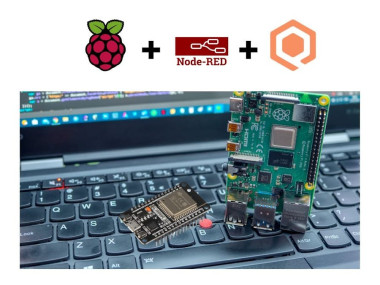
Will guide you to control the ESP32 LED via Node-Red and Raspberry Pi.
Project info
Difficulty: Moderate
Platforms: Raspberry Pi, Espressif, Node-RED
Estimated time: 1 hour
License: GNU General Public License, version 3 or later (GPL3+)
Story
In this tutorial, you will learn how to use Node-RED, a visual programming tool for the Internet of Things (IoT), to control an LED on an ESP32 board with a Raspberry Pi as the MQTT broker. MQTT is a lightweight and simple messaging protocol that allows devices to communicate with each other over a network.
You will need the following components for this project:
- ESP32 development board
- USB cable to connect the ESP32 to your computer
- Raspberry Pi with Node-RED
- Computer with Arduino IDE and PubSubClient library installed
You must check out PCBWAY for ordering PCBs online for cheap!
You get 10 good-quality PCBs manufactured and shipped to your doorstep for cheap. You will also get a discount on shipping on your first order. Upload your Gerber files onto PCBWAY to get them manufactured with good quality and quick turnaround time. PCBWay now could provide a complete product solution, from design to enclosure production. Check out their online Gerber viewer function. With reward points, you can get free stuff from their gift shop.
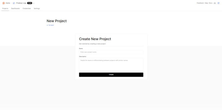
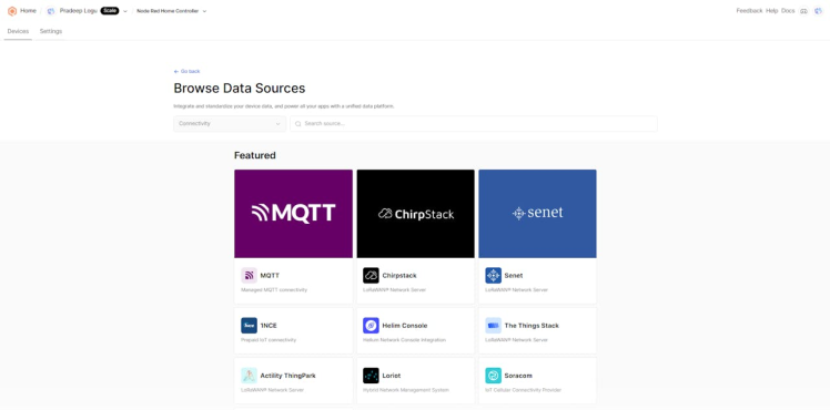
Step 1: Create a Device on QubitroThe first step is to create a device on the Qubitro platform. A device represents your physical device (Raspberry Pi) on the cloud. You need to create a device to obtain the MQTT credentials and topics for your Raspberry Pi.
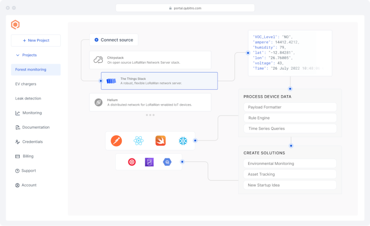
To create a device on Qubitro, follow these steps:
1. Log in to your Qubitro account and create a new project
2. Then go to the Devices page, select MQTT as the communication protocol, and click Next.
3. Enter all the details.
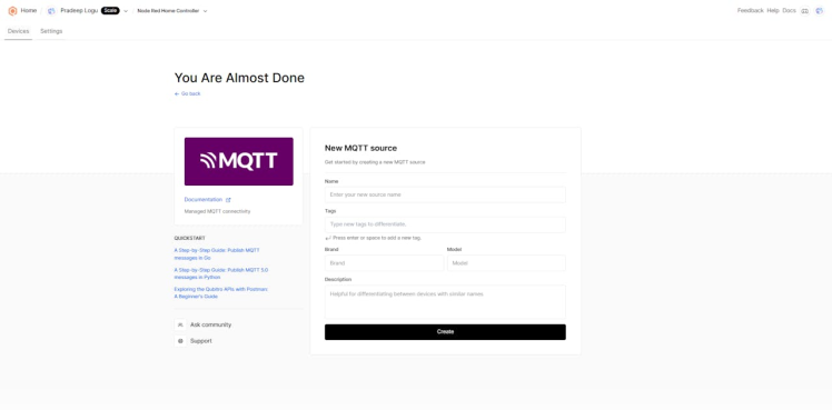
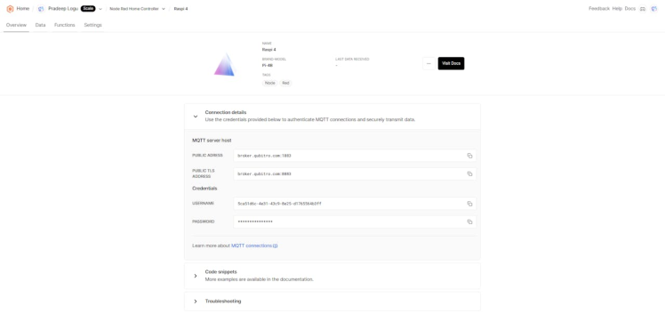
4. Copy the Device ID, Device Token, Hostname, Port, Publish Topic, and Subscribe Topic. You will need these values later in the code. Click Finish.
You have successfully created a device on Qubitro. You can see your device on the Devices page.
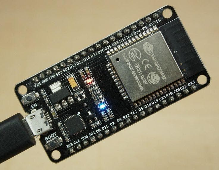
Step 2: Flash ESP32 with Arduino IDEThe ESP32 is a powerful and versatile microcontroller that can run Arduino code. You will use the Arduino IDE to program the ESP32 and make it communicate with the MQTT broker using the PubSubClient library.
To install the ESP32 board in Arduino IDE, you can follow the instructions in this tutorial or use the steps below:
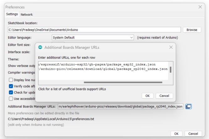
- Open the preferences window from the Arduino IDE: File > Preferences.
- Go to the “Additional Board Manager URLs” field and enter the following URL: https://dl.espressif.com/dl/package_esp32_index.json.
- Open Boards Manager (Tools > Board > Boards Manager), search for ESP32, and click the install button for the “ESP32 by Espressif Systems”.
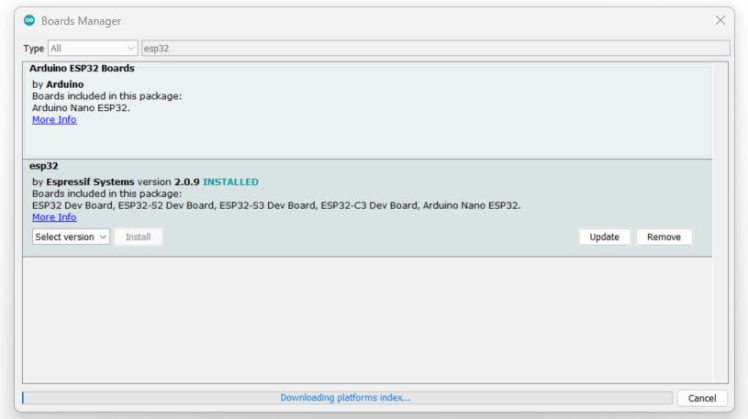
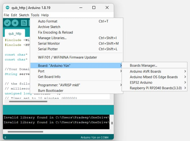
- Select your ESP32 board from Tools > Board menu after installation.
- Open the library manager from Sketch > Include Library > Manage Libraries.
- Search for PubSubClient and click the install button for the “PubSubClient by Nick O’Leary”.
- Restart your Arduino IDE after installation.
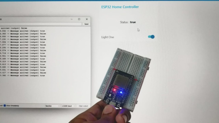
The LED is a simple device that emits light when current flows through it. You will connect the LED to one of the GPIO pins of the ESP32 and control its state (on or off) with MQTT messages.
In my case I'm going to use the onboard LED in the ESP32 Dev board.
The code for the ESP32 will do the following tasks:
- Connect to your Wi-Fi network
- Connect to the Qubitro MQTT broker on Raspberry Pi
- Receive messages from “output” and turn on or off the LED accordingly
You can copy and paste the code below into your Arduino IDE. Make sure to replace <your_ssid>, <your_password>, <your_Qubtro_Credientials> with your own values.
#include <WiFi.h>
#define DEBUG_SW 1
#include <PubSubClient.h>

//Relays for switching appliances
#define Relay1            2

int switch_ON_Flag1_previous_I = 0;

// Update these with values suitable for your network.

const char* ssid = "ELDRADO";
const char* password = "amazon123";
const char* mqtt_server = "broker.qubitro.com"; // Local IP address of Raspberry Pi

const char* username = "";
const char* pass = "";

// Subscribed Topics
#define sub1 "output"

WiFiClient espClient;
PubSubClient client(espClient);
unsigned long lastMsg = 0;
#define MSG_BUFFER_SIZE  (50)
char msg[MSG_BUFFER_SIZE];
int value = 0;


// Connecting to WiFi Router

void setup_wifi()
{

  delay(10);
  // We start by connecting to a WiFi network
  Serial.println();
  Serial.print("Connecting to ");
  Serial.println(ssid);

  WiFi.mode(WIFI_STA);
  WiFi.begin(ssid, password);

  while (WiFi.status() != WL_CONNECTED) {
    delay(500);
    Serial.print(".");
  }

  randomSeed(micros());

  Serial.println("");
  Serial.println("WiFi connected");
  Serial.println("IP address: ");
  Serial.println(WiFi.localIP());
}

void callback(char* topic, byte* payload, unsigned int length)
{
  Serial.print("Message arrived [");
  Serial.print(topic);
  Serial.print("] ");


  if (strstr(topic, sub1))
  {
    for (int i = 0; i < length; i++)
    {
      Serial.print((char)payload[i]);
    }
    Serial.println();
    // Switch on the LED if an 1 was received as first character
    if ((char)payload[0] == 'f')
    {
      digitalWrite(Relay1, LOW);   // Turn the LED on (Note that LOW is the voltage level
      // but actually the LED is on; this is because
      // it is active low on the ESP-01)
    } else {
      digitalWrite(Relay1, HIGH);  // Turn the LED off by making the voltage HIGH
    }
  }
  else
  {
    Serial.println("unsubscribed topic");
  }

}


// Connecting to MQTT broker

void reconnect()
{
  // Loop until we're reconnected
  while (!client.connected()) {
    Serial.print("Attempting MQTT connection...");
    // Create a random client ID
    String clientId = "ESP8266Client-";
    clientId += String(random(0xffff), HEX);
    // Attempt to connect
    if (client.connect(clientId.c_str() , username, pass)) {
      Serial.println("connected");
      // Once connected, publish an announcement...
      client.publish("outTopic", "hello world");
      // ... and resubscribe
      client.subscribe(sub1);
    } else {
      Serial.print("failed, rc=");
      Serial.print(client.state());
      Serial.println(" try again in 5 seconds");
      // Wait 5 seconds before retrying
      delay(5000);
    }
  }
}


void setup()
{

  pinMode(Relay1, OUTPUT);
  Serial.begin(115200);
  setup_wifi();
  client.setServer(mqtt_server, 1883);
  client.setCallback(callback);
}

void loop()
{

  if (!client.connected())
  {
    reconnect();
  }
  client. Loop();
}
After writing the code, upload it to your ESP32 board by selecting the right board and port from the Tools menu and clicking the upload button.
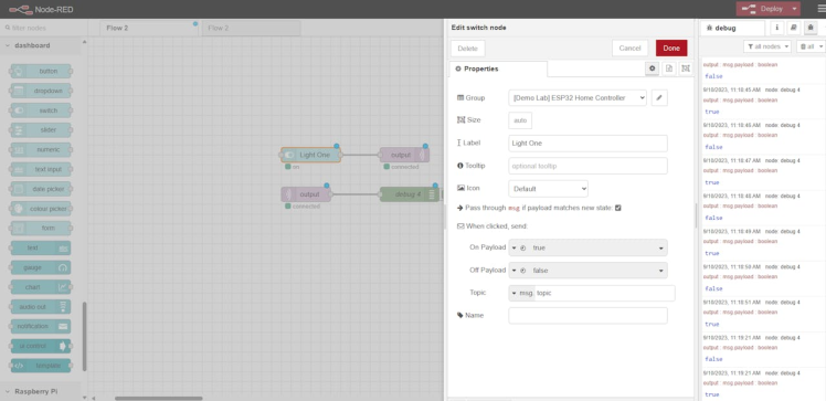
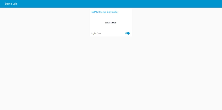
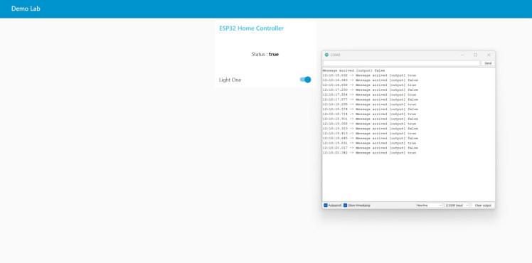
Step 5: Create Node-RED FlowThe Node-RED flow will do the following tasks:
- Connect to the MQTT broker on Raspberry Pi
- Subscribe to a topic named “output”
- Publish messages “true” or “false” to a topic named “output”
- Create a dashboard with a button and a text node
You can create the Node-RED flow by dragging and dropping nodes from the palette and connecting them with wires. You can also import the flow from this link or use the JSON code below:
[
    {
        "id": "eb8f9c0d054be30c",
        "type": "tab",
        "label": "Flow 2",
        "disabled": false,
        "info": "",
        "env": []
    },
    {
        "id": "4ce6cd876fd5441f",
        "type": "mqtt out",
        "z": "eb8f9c0d054be30c",
        "name": "",
        "topic": "output",
        "qos": "",
        "retain": "",
        "respTopic": "",
        "contentType": "",
        "userProps": "",
        "correl": "",
        "expiry": "",
        "broker": "6d40b7b21c734b53",
        "x": 870,
        "y": 240,
        "wires": []
    },
    {
        "id": "974a7a8bb6db9bf9",
        "type": "mqtt in",
        "z": "eb8f9c0d054be30c",
        "name": "",
        "topic": "output",
        "qos": "2",
        "datatype": "auto-detect",
        "broker": "6d40b7b21c734b53",
        "nl": false,
        "rap": true,
        "rh": 0,
        "inputs": 0,
        "x": 670,
        "y": 320,
        "wires": [
            [
                "d0dc7378c7bfb03b",
                "f1219a2eeabe825f"
            ]
        ]
    },
    {
        "id": "d0dc7378c7bfb03b",
        "type": "debug",
        "z": "eb8f9c0d054be30c",
        "name": "debug 4",
        "active": true,
        "tosidebar": true,
        "console": false,
        "tostatus": false,
        "complete": "payload",
        "targetType": "msg",
        "statusVal": "",
        "statusType": "auto",
        "x": 880,
        "y": 320,
        "wires": []
    },
    {
        "id": "6bd227b280e372b7",
        "type": "ui_switch",
        "z": "eb8f9c0d054be30c",
        "name": "",
        "label": "Light One",
        "tooltip": "",
        "group": "cd687a95.00e108",
        "order": 0,
        "width": 0,
        "height": 0,
        "passthru": true,
        "decouple": "false",
        "topic": "topic",
        "topicType": "msg",
        "style": "",
        "onvalue": "true",
        "onvalueType": "bool",
        "onicon": "",
        "oncolor": "",
        "offvalue": "false",
        "offvalueType": "bool",
        "officon": "",
        "offcolor": "",
        "animate": false,
        "x": 680,
        "y": 240,
        "wires": [
            [
                "4ce6cd876fd5441f"
            ]
        ]
    },
    {
        "id": "f1219a2eeabe825f",
        "type": "ui_text",
        "z": "eb8f9c0d054be30c",
        "group": "cd687a95.00e108",
        "order": 1,
        "width": "6",
        "height": "2",
        "name": "",
        "label": "Status : ",
        "format": "{{msg.payload}}",
        "layout": "row-center",
        "x": 1060,
        "y": 320,
        "wires": []
    },
    {
        "id": "6d40b7b21c734b53",
        "type": "mqtt-broker",
        "name": "Qubitro Downlink",
        "broker": "broker.qubitro.com",
        "port": "1883",
        "clientid": "",
        "autoConnect": true,
        "usetls": false,
        "protocolVersion": "4",
        "keepalive": "60",
        "cleansession": true,
        "autoUnsubscribe": true,
        "birthTopic": "r43MsJYzcVwZtUXVfZo6XD0Ym7CRegewPQXMt$ho",
        "birthQos": "0",
        "birthPayload": "",
        "birthMsg": {},
        "closeTopic": "",
        "closeQos": "0",
        "closePayload": "",
        "closeMsg": {},
        "willTopic": "",
        "willQos": "0",
        "willPayload": "",
        "willMsg": {},
        "userProps": "",
        "sessionExpiry": ""
    },
    {
        "id": "cd687a95.00e108",
        "type": "ui_group",
        "name": "ESP32 Home Controller",
        "tab": "aa146f4d.b53ca",
        "order": 1,
        "disp": true,
        "width": "6",
        "collapse": false
    },
    {
        "id": "aa146f4d.b53ca",
        "type": "ui_tab",
        "name": "Demo Lab",
        "icon": "dashboard",
        "order": 1,
        "disabled": false,
        "hidden": false
    }
]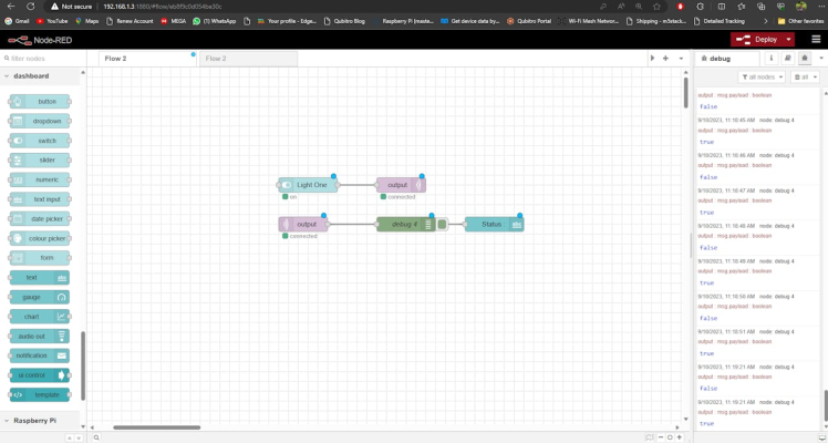
The input switch will send "true" when it is on, and it will send "false" when it triggers off.
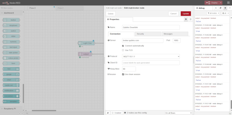
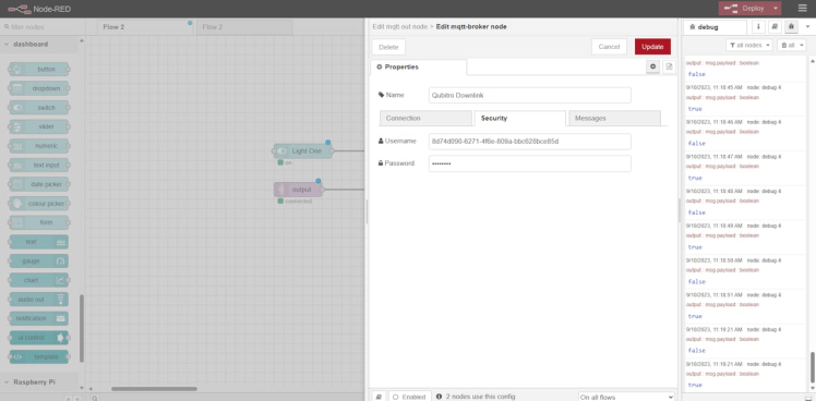
Then click on the Qubitro uplink pallet and edit the property.

Here you need to replace your connection details and credentials.
Next, just deploy the flow. And navigate to the /ui of the node-red server.
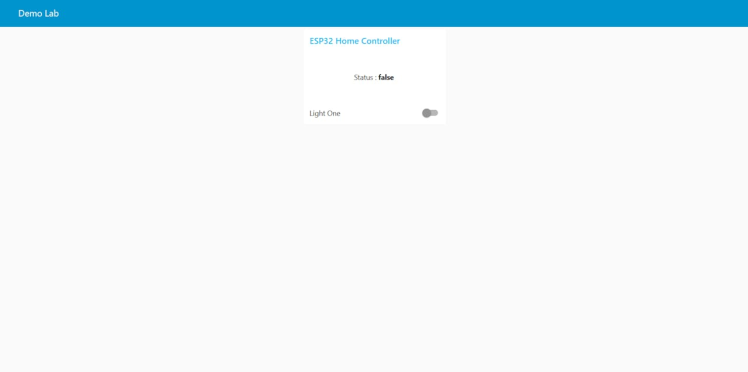
Here you can toggle the switch to turn the lead on and off.
Also, open the serial monitor and check the node-red response.
In this tutorial, we have seen how to control the LED with Node-Red and MQTT Server.
Credits
Related products


Leave your feedback...