
Nixie Clock With Arduino | Simplest Design

Made by engineer2you / Clocks
About the project
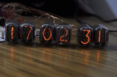
After long day working, finally I got successful making Nixie clock with Arduino and opto-isolation chip, no need Nixie driver which is difficult to purchase.
Project info
Difficulty: Moderate
Platforms: Arduino
Estimated time: 4 hours
License: GNU Lesser General Public License version 3 or later (LGPL3+)
Items used in this project

Story
I made instruction video for the project, please watch for full instruction:
Step 1: Part List


Part list to make project:
1. Arduino UNO https://amzn.to/2P58O7s
2. Nixie tube 6 pcs https://amzn.to/3aHyJvX
4. DC step-up module from 12VDC to 390VDC https://amzn.to/3aHyJvX
5. Breadboard https://amzn.to/3aHyJvX
6. Real time clock module DS3231 https://amzn.to/3aHyJvX
Step 2: Circuit Design

The circuit uses opto-isolation chip to control Nixie tube (using 150VDC) by Arduino (using 5VDC). By matrix connection, so we need only 16 outputs from Arduino to control 60 lights of 6 nixie tube.
The real time clock module DS3231 is used to keep the time (even turn off power), it is communicated with Arduino by I2C network.
Arduino will read real time, then turn on/off nixie lights by sequence in high frequency to make human eyes view 6 numbers as permanent
Step 3: Arduino Code

Basically, the code will get real time from module DS3231 and show to 6 nixie tube via opto-isolation chip.
Code and circuit can be downloaded here:http://bit.ly/2tUWtMy
Step 4: Build the Circuit


This is just experiment, so I made everything in bread board. Fortunately, it works at first time, no any problem
In next project, I will try to make nixie clock in MDF case with good decoration, so I can put it in my room.
Credits
Related products


Leave your feedback...