
Modeling And Simulation Electronic Circuits Using Python

Made by Aula_Jazmati
About the project
#️⃣ The project aims to model and simulate electronic circuits using Python and Raspberry Pi #️⃣
Project info
Difficulty: Moderate
Platforms: Raspberry Pi, PCBWay
Estimated time: 1 hour
License: MIT license (MIT)
Items used in this project
Hardware components

Story
Modeling and simulation in Python using a Raspberry Pi or a PC is a powerful tool for engineers and scientists to analyze and understand complex systems. Python is a popular programming language for its simplicity and readability, making it an ideal choice for modeling and simulation tasks.
To get started with modeling and simulation in Python, you can use libraries such as NumPy, SciPy, and SimPy to perform mathematical operations, solve differential equations, and simulate discrete-event systems. These libraries provide a wide range of functions and tools to create accurate models of electronic circuits, control systems, or any other dynamic system.
For example, you can use NumPy to define the behavior of electronic components such as diodes or transistors by creating mathematical models that represent their characteristics. Then, you can use SciPy to solve these models and simulate the response of the circuit under different conditions.
Once you have the simulation results, you can visualize them using the matplotlib library to create plots and graphs that show the behavior of the system over time or under different input conditions. This allows you to analyze the performance of your model and make informed decisions about its design or operation.
Using a Raspberry Pi for modeling and simulation offers the advantage of a low-cost platform that can be easily integrated with hardware components such as sensors or actuators. This allows you to create real-time simulations that interact with physical devices, providing a more realistic representation of the system under study.
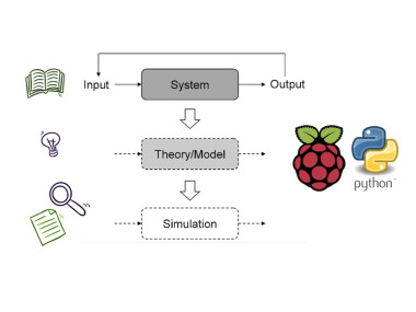
Relationship between a System, a Theory/Model, and a Simulation

Relationship between a System, a Theory/Model, and a Simulation
? Description:Modeling and simulation in Python can be done using the Raspberry Pi or any PC. Python provides various libraries and tools for modeling and simulating electronic circuits, such as numpy for numerical computations and matplotlib for data visualization.
#️⃣ To model and simulate a circuit using Python, you can follow these general steps:
1. Define the circuit: Identify the components of the circuit and their interconnections. This can be done using circuit diagrams or written descriptions.
2. Choose a modeling approach: Decide on the appropriate modeling approach for the circuit. This could involve using mathematical equations, circuit simulation software, or creating a custom simulation in Python.
3. Implement the model: Write the necessary Python code to represent the circuit components and their behavior. This may involve defining functions, classes, and data structures to capture the circuit's behavior.
4. Simulate the circuit: Use the implemented model to simulate the behavior of the circuit over time or in response to specific inputs. This could involve running simulations and analyzing the results.
5. Visualize the results: Use Python's data visualization libraries, such as matplotlib, to plot the input and output signals, voltage waveforms, current waveforms, or any other relevant data from the simulation.
#️⃣ By following these steps, you can effectively model and simulate electronic circuits using Python. This approach can be useful for understanding circuit behavior, testing designs, and prototyping electronic systems before physical implementation ??
? Full Wave Rectifier Example:This circuit uses four diodes in a bridge configuration to rectify both halves of the input sine wave.
Full Wave Rectifier

Full Wave Rectifier
If Vin > 2Vk    =>   Vo = Vin -2Vk
If Vin < -2Vk    =>   Vo = -Vin -2Vk
If -2Vk <= Vin <= 2Vk    =>   Vo = 0
------------------------------------------
Io = Vo/R
? Python code:
import numpy as np
import matplotlib.pyplot as plt

def FR(input_signal, vk):
    output_signal = input_signal.copy()
    for i in range(len(output_signal)):
        if output_signal[i] > 2*vk:
            output_signal[i] =  output_signal[i]- 2*vk
        elif output_signal[i] < - 2*vk:
            output_signal[i] = - output_signal[i] - 2*vk
        else:
            output_signal[i] =0
    return output_signal


Rl= 5
vk = 0.7
t = np.linspace(0, 2*np.pi, 1000)
v_in = 10*np.sin(t)
v_out = FR(v_in,vk)
Io= v_out/Rl

plt.plot(t, Io,'b', label='Current(A)')
plt.plot(t, v_in,'g', label='Input Voltage Signal (V)')
plt.plot(t, v_out,'r', label='Output Voltage Signal (V)')
plt.legend()
plt.xlabel('Time(s)')
plt.title('Full Wave Rectifier Circuit Simulation')
plt.show()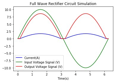
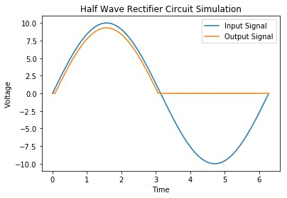
This circuit uses a diode, a device that conducts current in only one direction. It takes AC input and "rectifies" it so that the negative portion of the output is removed.
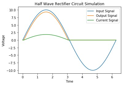
Half Wave Rectifier

Half Wave Rectifier
If Vin > Vk    =>   Vo = Vin -Vk
If Vin <= Vk   =>   Vo = 0
------------------------------------------
Io = Vo/R
? Python code:
import numpy as np
import matplotlib.pyplot as plt

def half_wave_rectifier(input_signal, threshold_voltage):
    output_signal = np.where(input_signal > threshold_voltage, input_signal - threshold_voltage, 0)
    return output_signal

t = np.linspace(0, 2*np.pi, 1000)
v_in = 10* np.sin(t)
V_threshold = 0.7
v_out = half_wave_rectifier(v_in, V_threshold)

#Plot of signals
plt.plot(t, v_in, label='Input Signal')
plt.plot(t, v_out, label='Output Signal')
plt.xlabel('Time')
plt.ylabel('Voltage')
plt.title('Half Wave Rectifier Circuit Simulation')
plt.legend()
plt.show()
1 / 2
The most general form of the diode clipper is shown in the figure below. For an ideal diode, the clipping occurs at the level of the clipping voltage, V1 and V2. However, the voltage sources have been adjusted to account for the 0.7 V forward drop of the real silicon diodes.
If Vin > E1+ Vk    =>   Vo = E1+ Vk
If Vin < -(E2+ Vk)    =>   Vo = -(E2+ Vk)
If -(E2+ Vk)  <= Vin <= (E2+ Vk)   =>   Vo = Vin
------------------------------------------
Io = Vin-Vo/R
Clipper Circuit Diagram

Clipper Circuit Diagram
? Python code:
import numpy as np
import matplotlib.pyplot as plt
#E1 = E2 = V_clip
def diode_clipper(input_signal, V_clip, Vk):
    output_signal = input_signal.copy()
    for i in range(len(output_signal)):
        if output_signal[i] > V_clip+Vk:
            output_signal[i] = V_clip+Vk
        elif output_signal[i] < -V_clip -Vk:
            output_signal[i] = -V_clip -Vk
    return output_signal

t = np.linspace(0, 2*np.pi, 1000)
v_in = 10*np.sin(t)
v_out = diode_clipper(v_in, 3,0.7)

plt.plot(t, v_in, label='Input Signal')
plt.plot(t, v_out, label='Output Signal')
plt.xlabel('Time')
plt.ylabel('Voltage')
plt.title('Diode Clipper Circuit Simulation')
plt.legend()
plt.show()
This is the most widely used method for biasing and stabilizing transistors. In this method, two resistors R1 and R2 are connected to the supply voltage VCC and provide bias. Emitter resistor RE provides stabilization. The name "voltage divider" comes from the voltage divider consisting of resistors R1 and R2.
1 / 2 • Voltage Divider Bias of a BJT

Voltage Divider Bias of a BJT

How to solve the voltage divider bias circuit
? Python code:
def VoltageDividerBJT(vcc,R1,R2,RE,RC,B,VBE,VCEsat):
    Rth=R1*R2/(R1+R2)
    vth=vcc*R2/(R1+R2)
    IB=(vth-VBE)/(Rth+(1+B)*RE)
    ICsat= (vcc-VCEsat) /(RC+RE)
    IC=B*IB
    if ((IC < ICsat) and (IC > 0)):
        IC=B*IB
        VCE=vcc-IC*(RE+RC)
        print('The transistor is in the Active mode')
    elif( IC>=ICsat):
        IC=ICsat
        VCE=VCEsat
        print('The transistor is in the Saturation mode')
    else:
        IB=0
IC=0
        VCE=vcc
        print('The transistor is in the cut-off mode')
    Pc=IC*VCE
    return (IB,IC,VCE,Pc)
#Example
vcc = 20  #v
RB1 = 100  # Kohm
RB2 = 10  # Kohm
RC = 3   # Kohm
RE = 1   # Kohm
B = 100
VBE = 0.7  #v
VCEsat=0 #v

IB,IC,VCE,Pc = VoltageDividerBJT(vcc,RB1,RB2,RE,RC,B,VBE,VCEsat)
print('IB=',IB)
print('IC=',IC)
print('VCE=',VCE)
print('Pc=',Pc)
The Results

The Results
#️⃣ In summary, modeling and simulation in Python is an effective approach for understanding complex systems in various engineering fields. By combining mathematical modeling with simulation techniques and visualization tools, you can gain valuable insights into the behavior of electronic circuits and other dynamic systems.
These models also benefit students in universities and schools to invest in Raspberry Pi and Python as a powerful educational tools ???

Code
Credits
Related products


Leave your feedback...