
Make Wi-Fi Controller Car Using Esp8266

Made by rau7han
About the project
We are going to talk about how to Make Internet or Wi-Fi Controller Car Using Esp8266. this can be easily controlled by your smartphone.
Items used in this project
Hardware components

Story
Hello guys, welcome back. In this tutorial, we are going to talk about how to Make Internet or Wi-Fi Controller Car Using Esp8266. this can be easily controlled by your smartphone. We have described to you step-by-step how to do this through this tutorial.
This WiFi Controlled Robot is made using ESP8266 Chip as a control unit. To control the pair of Motors, we used L298n Motor Driver IC Module.
We can power on the circuit using any battery as the power requirement is more than 5V. I mean a robotic car that is controlled over a WiFi Network.
Thank You NextPCB
Guys if you have a PCB project, please visit their website and get exciting discounts and coupons.
Free shipping 0$ PCB Prototype:https://www.nextpcb.com/pcb-quote?
Thanksgiving Christmas lucky draw 100% win: https://www.nextpcb.com/christmas-lucky-draw
Let's get started!
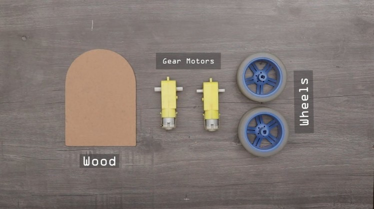
Required Components
1 / 2

- ESP8266 : https://amzn.to/3GqzjwW
- Wheels : https://amzn.to/3dxLfk4TT
- Gear Motor : https://amzn.to/3dxLfk4TT
- Li-Po Battery : https://amzn.to/3dxLfk4TT
- Battery Holder : https://amzn.to/3dxLfk4TT
- Wires : https://amzn.to/3dxLfk4TT
- wood : https://amzn.to/3dxLfk4TT
1 / 4
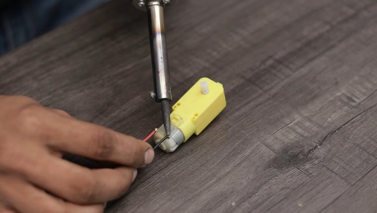
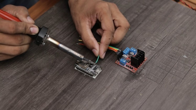
Solder a 10cm cable to the each terminal of motor.
Attach Motors to Acrylic
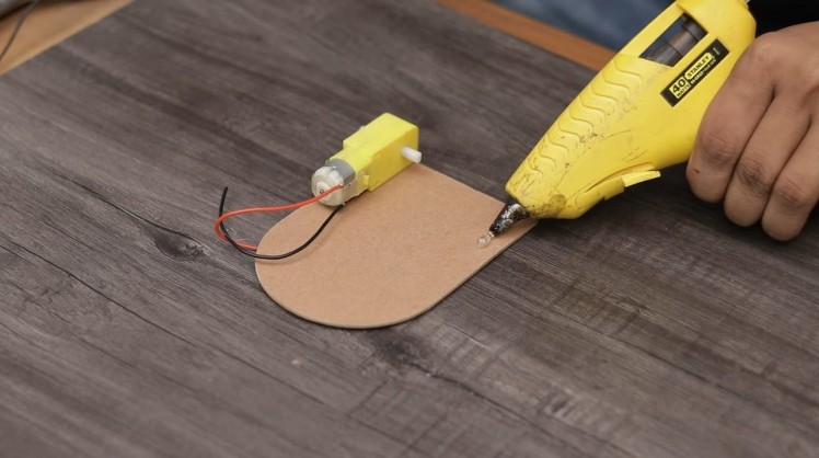
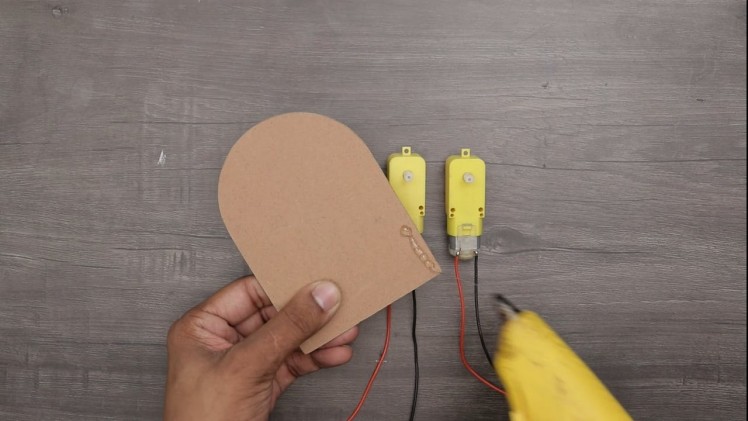
First Cut an foam or any kind of Board in a Preferred Dimension such as 14CM x 10CM. Make sure as photo.
Secondly, glue the four gear motors to the foam board, To do this, use the Glue gun.
Attach the motor to the acrylic using hot glue gun on all four sides of the acrylic as shown in the picture.
Pass the motor cable to the back through the acrylic hole.
Circuit Diagram
1 / 2
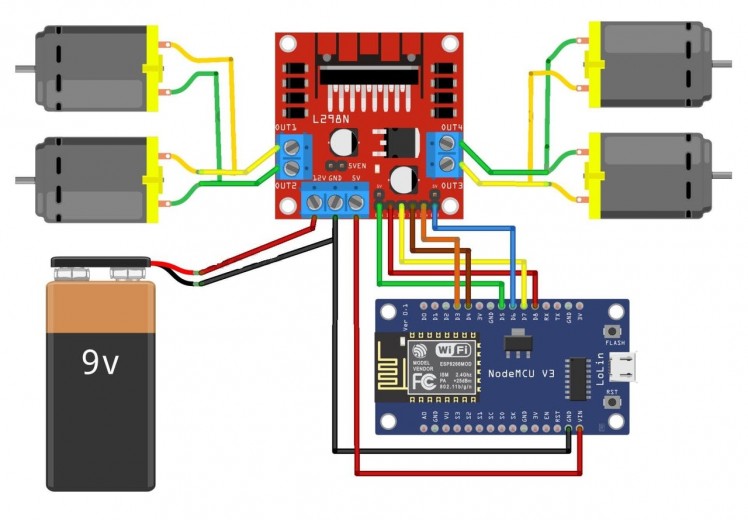

Here is the schematic for this Wi-Fi Controller Car Using Esp8266 Project designed using Fritzing software. We will control the two DC motors via L298 Motor Driver IC. I used L298N. This is a high power motor driver capable of running 5V to 35V DC Motor at a maximum of 25W.
You can use 200-300 RPM DC Motor for this application. The main control unit is ESP8266 Board which connects and controls the entire circuit and equipment.
You Can Also Follow the Following Pin Mapping.Motor Driver-> ESP8266
1 / 3
- ENA GPIO14(D5)
- ENB GPIO12(D6)
- IN_1 GPIO15(D8)
- IN_2 GPIO13(D7)
- IN_3 GPIO2(D4)
- IN_4 GPIO0(D3)
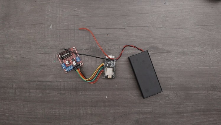
Connect the battery to the L298 Motor Driver power supply input. Connect all 6 inputs of L298 to ESP8266 D3, D4, D7, D8, D5 & D6 Pin. Supply 5V to Wemos through L298 5V Pin. Connect the output pins of L298 to left and right motors.
Attach the Motor
1 / 2
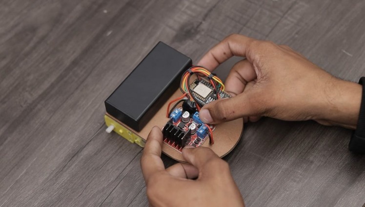
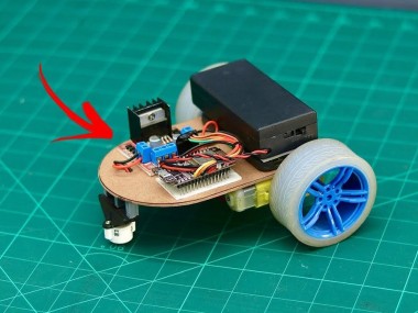
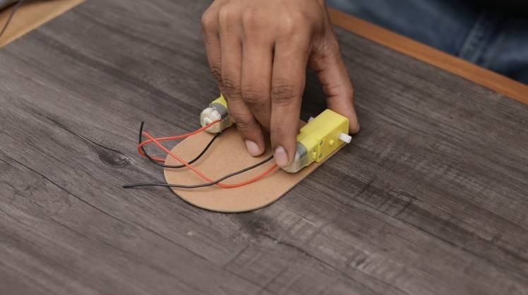
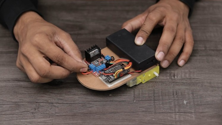
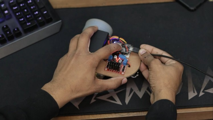
Thirdly, attach the motor driver board and Esp8266 to the top of the board I have used the cardboard. You can use metallic or wooden anything that fulfills your requirement.
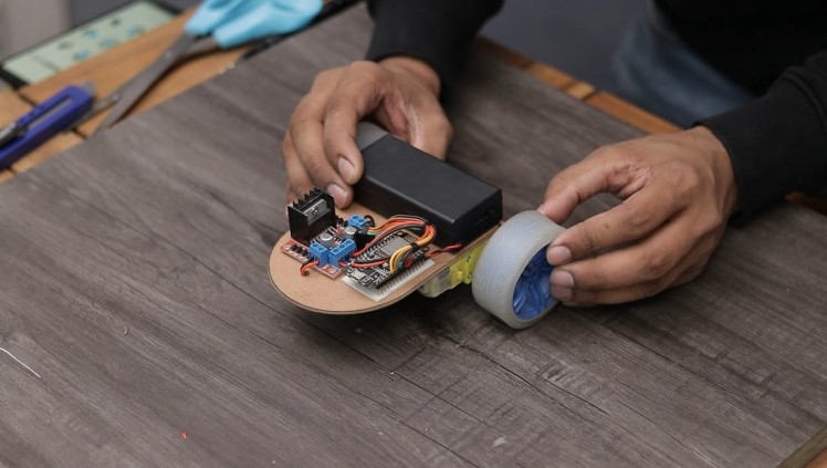
Tightly screw all the components and mount them on the chassis. Use good quality and strong wheels so that the robot can move even on rough surfaces.
Afterward, connect the gear motors to the Motor driver board. For that, use the above circuit diagram.
Source Code/Program
1 / 2
- copu, compiled and then Uploaded to NodeMCU Car.
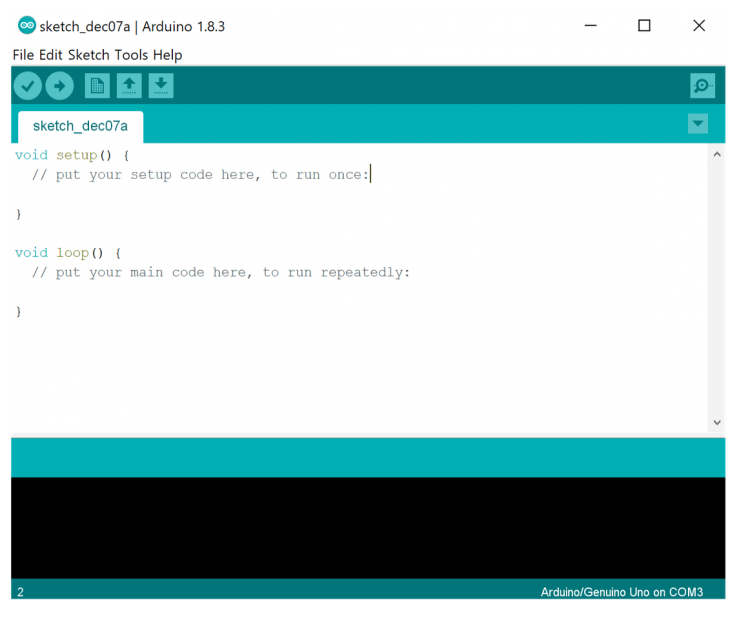
- The source program for WiFi Controlled car is very simple and you can program the ESP8266 Board using Arduino IDE.
- In this code part, change the WiFi SSID & Password from these lines.
const char* ssid = "DiYProjectslab"; const char* password = "Arduino";- Copy the complete code from below and get your ESP8266 Board for programming.
Additional Board Manager URL: http://arduino.esp8266.com/stable/package_esp8266c...
#define ENA   14          // Enable/speed motors Right        GPIO14(D5)
#define ENB   12          // Enable/speed motors Left         GPIO12(D6)
#define IN_1  15          // L298N in1 motors Rightx          GPIO15(D8)
#define IN_2  13          // L298N in2 motors Right           GPIO13(D7)
#define IN_3  2           // L298N in3 motors Left            GPIO2(D4)
#define IN_4  0           // L298N in4 motors Left            GPIO0(D3)

#include <ESP8266WiFi.h>
#include <WiFiClient.h>
#include <ESP8266WebServer.h>

String command;             //String to store app command state.
int speedCar = 800;         // 400 - 1023.
int speed_Coeff = 3;

const char* ssid = "Make DIY";
ESP8266WebServer server(80);

void setup() {

 pinMode(ENA, OUTPUT);
 pinMode(ENB, OUTPUT);
 pinMode(IN_1, OUTPUT);
 pinMode(IN_2, OUTPUT);
 pinMode(IN_3, OUTPUT);
 pinMode(IN_4, OUTPUT);

  Serial.begin(115200);

// Connecting WiFi

  WiFi.mode(WIFI_AP);
  WiFi.softAP(ssid);

  IPAddress myIP = WiFi.softAPIP();
  Serial.print("AP IP address: ");
  Serial.println(myIP);

 // Starting WEB-server
     server.on ( "/", HTTP_handleRoot );
     server.onNotFound ( HTTP_handleRoot );
     server.begin();
}

void goAhead(){

      digitalWrite(IN_1, LOW);
      digitalWrite(IN_2, HIGH);
      analogWrite(ENA, speedCar);

      digitalWrite(IN_3, LOW);
      digitalWrite(IN_4, HIGH);
      analogWrite(ENB, speedCar);
  }

void goBack(){

      digitalWrite(IN_1, HIGH);
      digitalWrite(IN_2, LOW);
      analogWrite(ENA, speedCar);

      digitalWrite(IN_3, HIGH);
      digitalWrite(IN_4, LOW);
      analogWrite(ENB, speedCar);
  }

void goRight(){

      digitalWrite(IN_1, HIGH);
      digitalWrite(IN_2, LOW);
      analogWrite(ENA, speedCar);

      digitalWrite(IN_3, LOW);
      digitalWrite(IN_4, HIGH);
      analogWrite(ENB, speedCar);
  }

void goLeft(){

      digitalWrite(IN_1, LOW);
      digitalWrite(IN_2, HIGH);
      analogWrite(ENA, speedCar);

      digitalWrite(IN_3, HIGH);
      digitalWrite(IN_4, LOW);
      analogWrite(ENB, speedCar);
  }

void goAheadRight(){

      digitalWrite(IN_1, LOW);
      digitalWrite(IN_2, HIGH);
      analogWrite(ENA, speedCar/speed_Coeff);

      digitalWrite(IN_3, LOW);
      digitalWrite(IN_4, HIGH);
      analogWrite(ENB, speedCar);
   }

void goAheadLeft(){

      digitalWrite(IN_1, LOW);
      digitalWrite(IN_2, HIGH);
      analogWrite(ENA, speedCar);

      digitalWrite(IN_3, LOW);
      digitalWrite(IN_4, HIGH);
      analogWrite(ENB, speedCar/speed_Coeff);
  }

void goBackRight(){

      digitalWrite(IN_1, HIGH);
      digitalWrite(IN_2, LOW);
      analogWrite(ENA, speedCar/speed_Coeff);

      digitalWrite(IN_3, HIGH);
      digitalWrite(IN_4, LOW);
      analogWrite(ENB, speedCar);
  }

void goBackLeft(){

      digitalWrite(IN_1, HIGH);
      digitalWrite(IN_2, LOW);
      analogWrite(ENA, speedCar);

      digitalWrite(IN_3, HIGH);
      digitalWrite(IN_4, LOW);
      analogWrite(ENB, speedCar/speed_Coeff);
  }

void stopRobot(){

      digitalWrite(IN_1, LOW);
      digitalWrite(IN_2, LOW);
      analogWrite(ENA, speedCar);

      digitalWrite(IN_3, LOW);
      digitalWrite(IN_4, LOW);
      analogWrite(ENB, speedCar);
 }

void loop() {
    server.handleClient();

      command = server.arg("State");
      if (command == "F") goAhead();
      else if (command == "B") goBack();
      else if (command == "L") goLeft();
      else if (command == "R") goRight();
      else if (command == "I") goAheadRight();
      else if (command == "G") goAheadLeft();
      else if (command == "J") goBackRight();
      else if (command == "H") goBackLeft();
      else if (command == "0") speedCar = 400;
      else if (command == "1") speedCar = 470;
      else if (command == "2") speedCar = 540;
      else if (command == "3") speedCar = 610;
      else if (command == "4") speedCar = 680;
      else if (command == "5") speedCar = 750;
      else if (command == "6") speedCar = 820;
      else if (command == "7") speedCar = 890;
      else if (command == "8") speedCar = 960;
      else if (command == "9") speedCar = 1023;
      else if (command == "S") stopRobot();
}

void HTTP_handleRoot(void) {

if( server.hasArg("State") ){
       Serial.println(server.arg("State"));
  }
  server.send ( 200, "text/html", "" );
  delay(1);
1 / 2

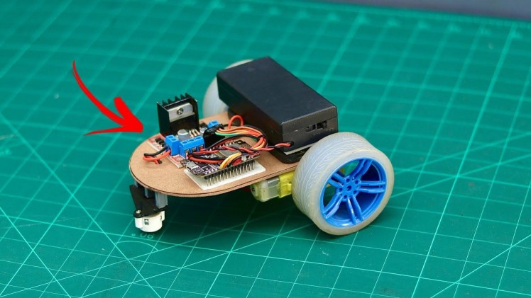
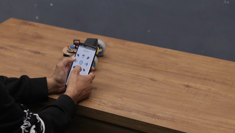
After uploading the code Open the Android App installed on your phone and connect with Wi-Fi Now you can control the Robot. To move the Robot in the forward direction, press the UP arrow key, and to move it backward, press the DOWN arrow key. Similarly, to move the Robot left and Right press the Left and Right arrow keys.
This is how you can make your own WiFi Controlled Robot and control the Robot using the Android Application.
Download App :- https://drive.google.com/drive/folders/
visit my website for more Tutorial :- https://www.diyprojectslab.com/
for more projects :- https://www.instructables.com/member/SmartTronix/
- You can make this project with advanced features like integrating a camera and accessing the feed live on the browser.
Thank You See You soon

Leave your feedback...