

Make TV Ambilight Using Arduino

Made by rau7han
About the project
hii, friends I hope you all are fine today i'll show you how to Make TV Ambilight Using Arduino This is a very easy project.
Project info
Difficulty: Moderate
Platforms: Digilent
Estimated time: 1 hour
License: Creative Commons Attribution-ShareAlike CC BY-SA version 4.0 or later (CC BY-SA 4+)
Items used in this project

Story
hii, friends I hope you all are fine today i'll show you how to Make TV Ambilight Using Arduino
This is a very easy project.
I won't go into too much detail how each part works, because I have written some information on my blog.
https://www.diyprojectslab.com/make-tv-ambilight-w...
But you should be able to make it work with the information given on this instructable.
- Ambibox Software on PC (free, but only Windows)
- Arduino with a simple script which uses the FastLed library (further down) (~3$)
- 50 RGB WS2811 LEDs (~13$)- optional power brick
This setup is very cheap but only works on a PC
This project is successfully completed because of the help and support from Nextpcb
Here are midsummer sales at NextPCB
1. Up to 30% off for PCB oders
2. Up to 20% off for PCBA oders
Only 0$ for 5-10pcs PCB Prototypes https://www.nextpcb.com/
NOTE
Linux or MAC is not supported. The Ambibox software I am using is only available on Windows.(For standalone applications there is an RPI variant, quite expensive)
The LEDs work quite good and without noticeable lag on the Desktop and while watching movies! Games are a different story.
If the game runs in Full screen mode, the software will most of the time not be able to capture the image.
But Borderless mode works! (keep in mind the added CPU power needed ~5%)
Step 1: Material Needed to Build.
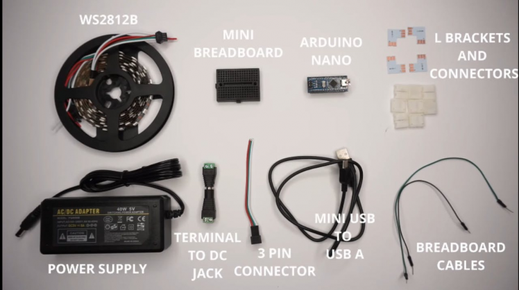
- LED strip WS2812B
- Arduino Nano
- mini breadboard
- Jumper wires
- Terminal to DC jack
- Mini USB to USB
- 5V power supply for the LEDs
- A computer
- Arduino IDE
- Programming cable
Thank You NextPCB:
This project is successfully completed because of the help and support from Nextpcb
Guys if you have a PCB project, please visit their website and get exciting discounts and coupons.
Only 0$ for 5-10pcs PCB Prototypes https://www.nextpcb.com.
Step 2: RGB LED.
1 / 2
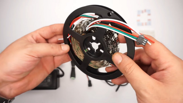
The most important part of this project are the RGB LEDs with individual controllers.The most important part of this project are the RGB LEDs with individual controllers.
It doesn't really matter which RGB LED Controller you get, as long these are supported by the FastLed library. Here is a link to the supported LED Chips: https://github.com/FastLED/FastLED/wiki/Overview
The most common are the WS2811 or WS2812 LEDs since there are cheap and easy to use.
These are also used in this project. They are sold in at least two different types: - as single bulbs (12mm) with a variable spacing of around 10cm at max.
You mostly get pairs of 50, but you can add or extract LEDs as you wish. -as LED strips (with adhesive on the back).
These you buy per meter with a fixed spacing. (30/60/or more LEDs per meter). With single bulb LEDs, you get the advantage of completely free positioning and spacing.
But on the other hand, you have to find a way to add them to your monitor.
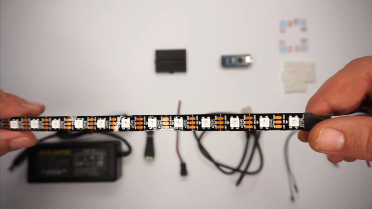
Step 3: Mount LED Strip on TV.
1 / 3
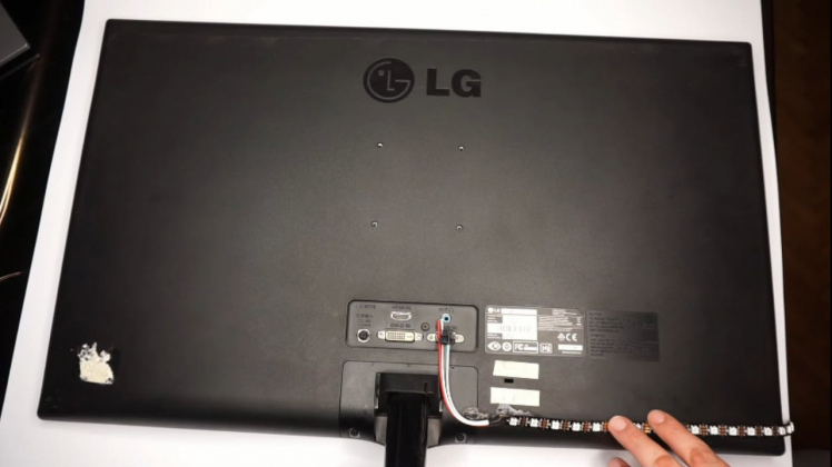
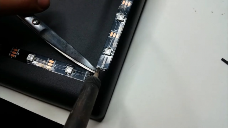
So first things first, measure the size of your monitor from behind, just to see how many LEDs from the strip you need to cut.
When measuring leave about 1cm from each edge, just to make sure the strip won't show when attached to the monitor.
Once you're satisfied with your measurement, cut the LED strip to length.
Each of these LEDs is individually addressable so you can cut after each LED at the marked cutting point (shown in the picture).
Go ahead and cut all 4 strips. Once done move to the next step.
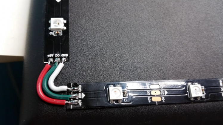
Once you've cut all your strips to size, it's time to re-connect them to act as a single 'flexible' strip.I used some stranded wire.
simply solder the +5v to the next +5v rail, the DIN to the next DIN and the GND to the next GND.
Once you've done that the strip should all be connected together in 4 parts.
Important TIP: Ensure that the led strip direction arrows are pointing in the correct orientation, otherwise nothing will wo
Step 4: Connecting the Arduino
1 / 2
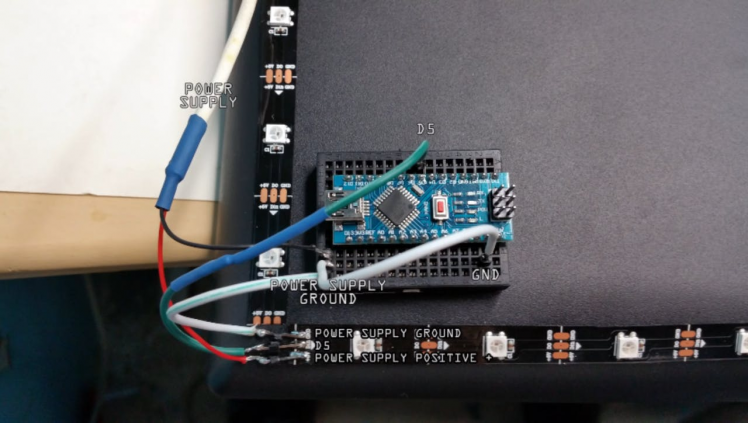
Connect the DIN pin to pin number 5 on the arduino board.
Mine came with some headers which I soldered on.
In the image I accidentally used a white wire for the ground and a black for data.
Don't get confused, the data wire from the strip needs to connect to the 4th pin on the arduino board.
Optional: You can connect the GND pin from the arduino to the PSU GND, this is useful if you're using a separate power source from your PCs PSU.
Next connect the arduino to your PC and install the necessary drivers (if any).
Assumption: You know how to compile the code to your arduino.
If not search the countless tutorials online :) Use the arduino programmer to compile and program the arduino board with the following code:
Step 5: The Connections

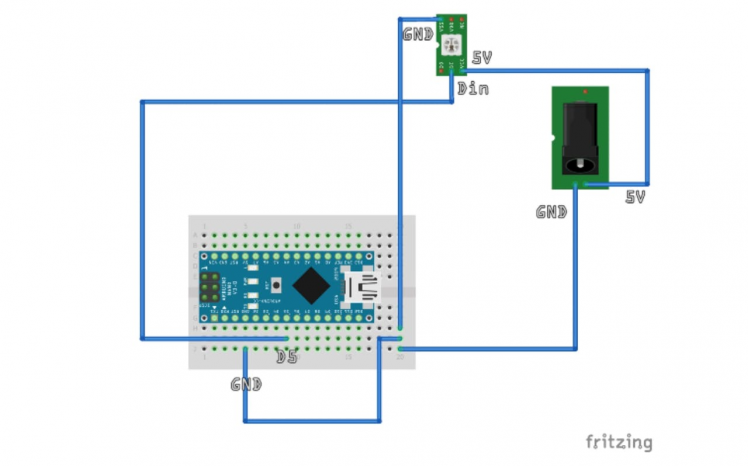
If you are using the WS2811/12 LEDs there are only 3 connections you have to make.
You have to connect the 5V Power with the corresponding 5V line on the LEDs.
You have to connect the ground of the PSU with the ground on the Arduino and the ground on the LEDs You have to connect the data line of the LEDs with one digital port of the Arduino.
Which one doesn't really matter, but you have to remember the number.
Step 6: SoftwareAdalight + Perismatic
Go below and download the Adalight code for the Arduino.
Open it in the Arduino IDE and make sure you have already installed the FastLED library before.
There in the code, all we have to do is to define the pin, in my case digital pin 4, and amount of LEDs, in my case 60.
Compile, select the COM port and upload the code to the Arduino.
here adjust each color till you match the color of your background wall, in my case white.
Click next and we are done. Now play any RGB test video that you’ll fint in the description and there you go
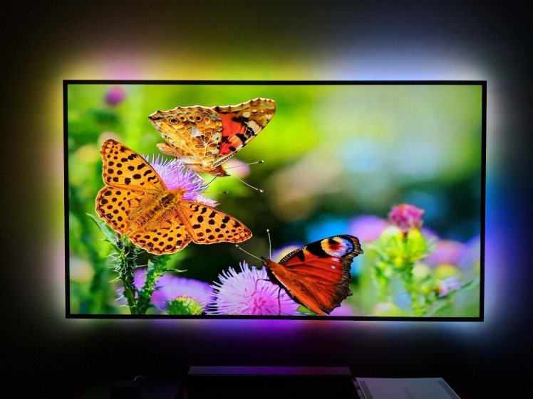
You can now watch movies with AMBILIGHT effects and that is awesome.
The application also has sound effect where the LEDs will blink according to the music you play.
visit My website DiY Projects Lab having more than 25 awesome detailed projects
Leave your feedback...