
Make An Edgeasketch With Meadow

Made by jorgedevs
About the project
Learn how to make your very own EdgeASketch with Meadow using a couple of Rotary encoders and a TFT SPI LCD display.
Project info
Difficulty: Easy
Platforms: Microsoft, Meadow, Wilderness Labs
Estimated time: 1 hour
License: MIT license (MIT)
Items used in this project
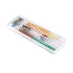
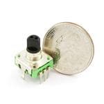
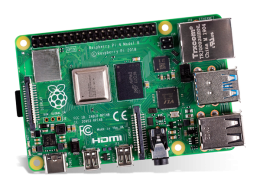
Hardware components
Story
In this Meadow project we're going to learn how to build the very popular retro drawing toy EdgeASketch using a couple of rotary encoders and a TFT SPI display. We'll see how easy is to write the logic using the powerful driver platform Meadow.Foundation and its GraphicsLibrary to do all the drawing.
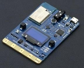
Everything you need to build this project is included in the Wilderness Labs Meadow F7 w/Hack Kit Pro. We'll see how easy is to program these peripherals using Meadow.Foundation.
Meadow.Foundationa platform for quickly and easily building connected things using.NET on Meadow. Created by Wilderness Labs, it's completely open source and maintained by the Wilderness Labs community.
If you're new working with Meadow, I suggest you go to the Getting Started w/ Meadow by Controlling the Onboard RGB LEDproject to properly set up your development environment.
Step 1 - Assemble the circuitWire up your EdgeASketch circuit like the Fritzing diagram below:
Fritzing Diagram for EdgeASketch with Meadow

Fritzing Diagram for EdgeASketch with Meadow
Note about interruptson Meadow F7
If you look at the diagram closely, you can see that we're wiring the top rotary encoder to Analog pins A0, A1 and A2. This is possible because you can actually configure these pins to be digital input ports to handle interrupts. Check this Meadow pinout diagram:
Meadow F7 Micro pinout

Meadow F7 Micro pinout
Notice the pins marked with an Interrupt Group range from group 00 to group 09. This is important to have in mind for when configuring digital input ports, you have to make sure that you're using only one pin per Interrupt Group, otherwise you will run into problems trying to get events. For example, you wont get interrupt events when configuring pins D14 and D15 since both belong to Interrupt Group 03.
Step 2 - Create a Meadow Application projectCreate a new Meadow Application project in Visual Studio 2019 for Windows or macOS and name it EdgeASketch.
Step 3 - Add the required NuGet packagesWindows
Right-click on your EdgeASketch project and click Manage NuGet Packages. In the Browse tab, search for Meadow.Foundation.Displays.TftSpi and click Install to add it to your project.
macOS
Alt-click on your EdgeASketch project in the Solution Explorer, and click Add => Add Nuget Package to open the NuGet Package window. Search for Meadow.Foundation.Displays.TftSpi and click Install to add it to your project.
Step 4 - Write the code for EdgeASketchCopy the following code below:
public class MeadowApp : App<F7Micro, MeadowApp>{ int x, y; St7789 st7789; GraphicsLibrary graphics; RotaryEncoderWithButtonrotaryX; RotaryEncoderWithButtonrotaryY; public MeadowApp() { x = y = 120; var config = new SpiClockConfiguration( speedKHz: 6000, mode: SpiClockConfiguration.Mode.Mode3); st7789 = new St7789( device: Device, spiBus: Device.CreateSpiBus( clock: Device.Pins.SCK, mosi: Device.Pins.MOSI, miso: Device.Pins.MISO, config: config), chipSelectPin: null, dcPin: Device.Pins.D01, resetPin: Device.Pins.D00, width: 240, height: 240); graphics = new GraphicsLibrary(st7789); graphics.Clear(true); graphics.DrawRectangle(0, 0, 240, 240, Color.White, true); graphics.DrawPixel(x, y, Color.Red); graphics.Show(); rotaryX = new RotaryEncoderWithButton(Device, Device.Pins.A00, Device.Pins.A01, Device.Pins.A02); rotaryX.Rotated += RotaryXRotated; rotaryY = new RotaryEncoderWithButton(Device, Device.Pins.D02, Device.Pins.D03, Device.Pins.D04); rotaryY.Rotated += RotaryYRotated; rotaryY.Clicked += RotaryYClicked; } void RotaryXRotated(object sender, RotaryTurnedEventArgs e) { if (e.Direction == RotationDirection.Clockwise) x++; else x--; if (x > 239) x = 239; else if (x < 0) x = 0; graphics.DrawPixel(x, y + 1, Color.Red); graphics.DrawPixel(x, y, Color.Red); graphics.DrawPixel(x, y - 1, Color.Red); graphics.Show(); } void RotaryYRotated(object sender, RotaryTurnedEventArgs e) { if (e.Direction == RotationDirection.Clockwise) y++; else y--; if (y > 239) y = 239; else if (y < 0) y = 0; graphics.DrawPixel(x + 1, y, Color.Red); graphics.DrawPixel(x, y, Color.Red); graphics.DrawPixel(x - 1, y, Color.Red); graphics.Show(); } void RotaryYClicked(object sender, EventArgs e) { x = y = 120; graphics.DrawRectangle(0, 0, 240, 240, Color.White, true); graphics.DrawPixel(x, y, Color.Red); graphics.Show(); }}Meadow Constructor
In the MeadowApp's Constructor, we first initialize the ST7789 SPI display along with the Graphics Library, We immediately draw a white filled rectangle that covers the entire screen, and draw a Red pixel in the middle of the display with the previously initialized x and y integers. We also initialize the two Rotary Encoders, one to control the draw on the X axis and the other to draw on the Y axis. Both rotaries have the Rotated event registered.
RotatyXRotated and RotatyYRotated event handlers
In the event handlers, you can check to which direction the rotary encoders were turned by accessing the e.Direction property and comparing with the enum RotationDirection to see if its Clockwise or CounterClockwise. If its Clockwise, we increment either the X or Y coordinates (depending which Rotaty was turned), and we would decrement if its turned the other way.
Notice we're drawing at three pixels at a time in both directions, we do this to make the line stroke a bit thicker, since the resolution of the display is so high, the drawing line is too thing, making it difficult to see what you're doing.
RotaryYClicked
Since we're using rotary encoders with buttons, you can handle Click event handlers, like you would do working with PushButtons. The RotaryYClicked event handler will clear the display and re-initialize the x and y coordinates back to the middle of the display.
Click the Run button in Visual Studio. It should look like to the following GIF:
EdgeASketh project running

EdgeASketh project running
Check out Meadow.Foundation!This project is only the tip of the iceberg in terms of the extensive exciting things you can do with Meadow.Foundation.
- It comes with a huge peripheral driver library with drivers for the most common sensors and peripherals.
- The peripheral drivers encapsulate the core logic and expose a simple, clean, modern API.
- This project is backed by a growing community that is constantly working on building cool connected things and are always excited to help new-comers and discuss new projects.
Schematics, diagrams and documents
Code
Credits
Related products


Leave your feedback...