
Make A Basic Level With An Mpu6050, Four Leds And Meadow

Made by jorgedevs
About the project
Learn how to read data from an MPU6050 accelerometer/gyro sensor and control LEDs with your Meadow F7 Micro board using Meadow. Foundation.
Project info
Difficulty: Easy
Platforms: Microsoft, Meadow, Wilderness Labs
Estimated time: 1 hour
License: Apache License 2.0 (Apache-2.0)
Items used in this project
Hardware components


Story
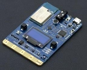
In this project we're going to learn how to use an MPU6050 sensor to detect slight inclinations on the x and y axis and the LED on the higher slope will turn on. Most of the components needed to build this project is included in the Wilderness Labs Meadow F7 w/Hack Kit Pro.
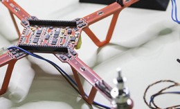
MPU6050 sensors are capable of providing much more data since they're packed with a 6 axis accelerometer and gyro, which are commonly used to quadrocopter drones and RC planes. You can easily communicate with them using I2C serial communication via serial clock (SCL) and data (SDA). We'll write the logic for the sensor and LEDs using Meadow.Foundation.
Meadow.Foundationa platform for quickly and easily building connected things using.NET on Meadow. Created by Wilderness Labs, it's completely open source and maintained by the Wilderness Labs community.
If you're new working with Meadow, I suggest you go to the Getting Started w/ Meadow by Controlling the Onboard RGB LEDproject to properly set up your development environment.
Step 1 - Assemble the circuitWire your LEDs and Mpu6050 project like the following circuit diagram:
Project circuit diagram

Project circuit diagram
Step 2 - Create a Meadow Application projectCreate a new Meadow Application project in Visual Studio 2019 for Windows or macOS and name it RotationDetector.
Step 3 - Add the required NuGet packagesWindows
Right-click on your RotationDetector project and click Manage NuGet Packages. In the Browse tab, search for Meadow.Foundation.Sensors.Motion.Mpu6050 and click Install to add it to your project.
macOS
Alt-click on your RotationDetector project in the Solution Explorer, and click Add => Add Nuget Package to open the NuGet Package window. Search for Meadow.Foundation.Sensors.Motion.Mpu6050 and click Install to add it to your project.
Step 4 - Write the code for RotationDetectorIn your MeadowApp class, copy the following code below:
using Meadow;using Meadow.Devices;using Meadow.Foundation.Leds;using Meadow.Foundation.Sensors.Motion;using Meadow.Peripherals.Sensors.Motion;namespace RotationDetector{ public class MeadowApp : App<F7Micro, MeadowApp> { Led up; Led down; Led left; Led right; Mpu6050 mpu; public MeadowApp() { var led = new RgbLed( Device, Device.Pins.OnboardLedRed, Device.Pins.OnboardLedGreen, Device.Pins.OnboardLedBlue); led.SetColor(RgbLed.Colors.Red); up = new Led(Device.CreateDigitalOutputPort(Device.Pins.D15)); down = new Led(Device.CreateDigitalOutputPort(Device.Pins.D12)); left = new Led(Device.CreateDigitalOutputPort(Device.Pins.D14)); right = new Led(Device.CreateDigitalOutputPort(Device.Pins.D13));mpu = new Mpu6050(Device.CreateI2cBus()); mpu.AccelerationChangeThreshold = 0.05f; mpu.Updated += MpuUpdated; mpu.StartUpdating(100); led.SetColor(RgbLed.Colors.Green); }void MpuUpdated(object sender, AccelerationConditionChangeResult e) { up.IsOn = (0.20 < e.New.YAcceleration && e.New.YAcceleration < 0.80); down.IsOn = (-0.80 < e.New.YAcceleration && e.New.YAcceleration < -0.20); left.IsOn = (0.20 < e.New.XAcceleration && e.New.XAcceleration < 0.80); right.IsOn = (-0.80 < e.New.XAcceleration && e.New.XAcceleration < -0.20); } }}In the MeadowApp's constructor we initialize all the LEDs and the MPU6050 sensor. Notice that for the LEDs we simply pass digital output port by calling Device.CreateDigitalOutputPort(IPin pin) along with Pin each LED is connected to, and for the Mpu6050 sensor, all we need to pass is a I2C bus calling Device.CreateI2cBus().
Note: To find the inclination values, simply print each value in the output console and rotate your circuit and write down the X and Y values which you consider to make each LED to turn on or off.
Step 5 - Run the projectClick the Run button in Visual Studio. It should look like to the following GIF:
Running RotationDetector value

Running RotationDetector value
Check out Meadow.Foundation!This project is only the tip of the iceberg in terms of the extensive exciting things you can do with Meadow.Foundation.
- It comes with a huge peripheral driver library with drivers for the most common sensors and peripherals.
- The peripheral drivers encapsulate the core logic and expose a simple, clean, modern API.
- This project is backed by a growing community that is constantly working on building cool connected things and are always excited to help new-comers and discuss new projects.
Schematics, diagrams and documents
Code
Credits
Related products


Leave your feedback...