
Magnetic Field Visualizer

Made by electrouser805
About the project
Utilizing TLV493D 3D Magnetic sensor to visualize a magnet's NS pole direction, heading, magnetic field line & strength on an E-ink Display.
Project info
Difficulty: Easy
Estimated time: 1 hour
License: GNU General Public License, version 3 or later (GPL3+)
Items used in this project
Hardware components


Story
About this project
This project is about developing a simple magnetic field visualizer. Here, the XMC1100 is the system mcu with fetches magnetic field data of a nearby magnet from the TLV49 3D magnetic sensor. The mcu communicates with the sensor over I2C protocol. For visualizing the data, an E-Ink/Epaper display is added to the system. The display is 3.3 volts like rest of the system and communicates with the host mcu over SPI.
The display has 200 x 200 pixels and support for Black in White or White in Black imaging. As for the 3D magnetic sensor, it can sense up to +/- 130 mT in X, Y, Z direction of the sensor itself.
 Display parameters
This visualizer can be used for :
- Identifying North/South poles of a magnet
- Magnet's orientation/heading on XY plane
- Visualize virtual Field lines
- Detect effective field area of a magnet
- Compare magnets strength qualitatively
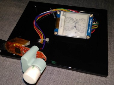
Step 1: Hardware Connection
Connecting the hardware is simple. The E-ink display is connected to the 2Go kit according to the schematic. The display operates on 3.3 volts, 4 wire SPI with few control lines.
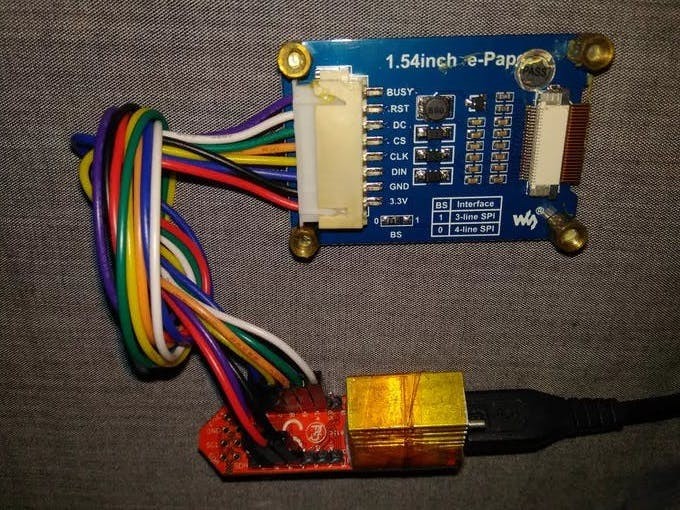 3 SPI I/O + 3 control I/O+ Vcc and Gnd
Now, the XMC2Go kit and the display is cable tied on a breadboard base.
Step 2: Programming
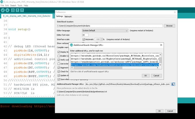
To program the system in Arduino IDE, the 2Go kit's board support must be added. This is done by following these steps -
- Install and run Arduino IDE 1.8.5
- Go to File > Preferences > Additional Board Manager URLs and paste https://github.com/Infineon/Assets/releases/download/current/package_infineon_index.json
 Adding 2Go kit support on Arduino IDE
- Now go to Tools > Board Manager > type "xmc" in search box and download board support files
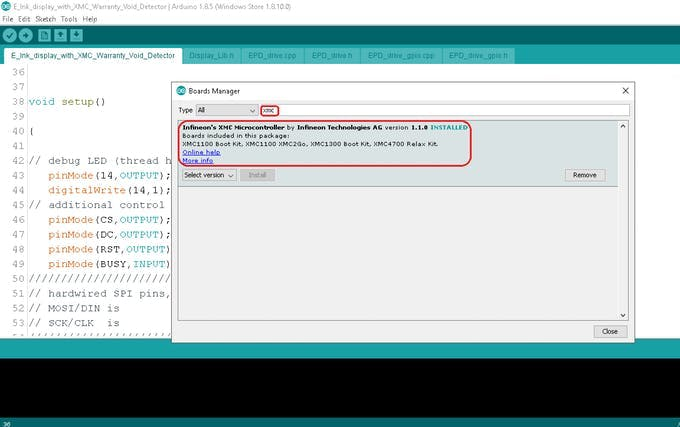 Install board files
- Now, we need Library for TLE493D 3D magnetic sensor.
Go to: https://github.com/IRNAS/TLV493D-3D-Magnetic-Sensor-Arduino-Library
Download the zip library and add to IDE
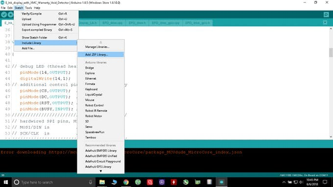 Adding Library
- Next, Install Segger Link for communication between kit and IDE from here:
https://www.segger.com/downloads/jlink/JLink_Windows_beta.exe
- Then, go to tools and set
Board : XMC1100XMC2Go
Serial Output Selection : On Board
Port : Port 11 (select whichever new port appears after plugging kit to usb )
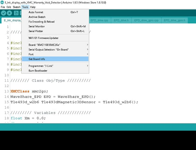 Setting up board, serial and program port
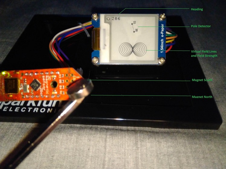
Step 3:Visualize Magnetic Field
Check out this video to find what happens when magnet is moved towards and away from the TLV 493 3D magnetic sensor.
Also, notice how rotating the magnet rotates the pole detector:
Visualization- Pole detector is in phase with actual magnet's NS poles
- Closer/Stronger the magnet, more field lines
- Heading sweeps from 0 to 360 for each full rotation of the magnet
What to expect?
- Visualization is only applicable to single, symmetric magnet. Not applicable for complex magnetic field. For such application multiple sensors are required with high speed mcu and display.
- The purpose of this visualizer is not quantitative measurements but qualitative ones, mostly for educational/entertainment purpose.
- N-S poles of a magnet is shown with Pole Detector which is in phase with two dynamic dots connected with a line. Pole Detector rotates as the magnet rotates. It can be used to identify the north and south poles of a magnet, given that the magnet is suspended closely top of the 3D magnetic sensor.
- 0 to 360 heading can be observed by rotating a magnet on the xy plane of the sensor.
- Number of field line represents magnet's strength for a given position. It is suitable to compare 2 magnets placed at the same distance from sensor and find out which is more strong. Field lines do not rotate with the rotation of the magnet ( I tried but couldn't figure out the mathematical jazz )
- The field lines are usually elliptic shaped, but due to API limitations, circular shaped field lines are used to represent field lines.
- Better understanding of physics, mathematics and programming can improve the project.
References
Schematics, diagrams and documents
Code
Credits
Related products


Leave your feedback...