
Psoc4: Low Cost Dds Function Generator For Makers

Made by electrouser805
About the project
Generating Sine, Square, Triangular, Sawtooth Waveform with Direct Digital Synthesizer method using PSoC 4 MCU and few passive components.
Project info
Difficulty: Moderate
Estimated time: 1 hour
License: GNU Lesser General Public License version 3 or later (LGPL3+)
Items used in this project
Hardware components


View all

Story
Basics
This project is about making a Direct Digital Synthesizer Function Generator that can sprout Sine, Square, Triangular, Saw waveforms. It's also possible to program other random waveform patterns.
Features
- 100 Hz - 20 kHz for Sine, Triangular, Sawtooth Wave
- 100 Hz - 50 kHz for Square Wave
- Adjustable Gain Control
- Adjustable Frequency Sweep
- One press Frequency Stepping
- One press Waveform Switching
- Automatic HF Harmonic Filtering
- Ground Offset Capability
- Maximum 8 Bit DDS Resolution
- Low Cost, maker friendly design
- Minimum External Components
- Programmable for Custom Waveform
Step 1: Working Principle
Direct digital synthesis (DDS) is a method of producing arbitrary waveform of any type using DAC.
The PSoC 4 has 2 internal IDACs or current DACs of 7 bit and 8 bit. For this device 8-bit IDAC is used because it provides better resolution.
To produce sine wave, there is a lookup table/array holding 256 value points of a full cycle sine wave. CPU reads those values and pass to IDAC to generate proportionate current. This current is drained through a resistor to generate corresponding voltage level. Finally that voltage is buffered through one of the internal Opamp to get the output signal.
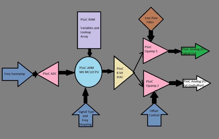 Functional Block Diagram
Since, IDAC requires few uS settling ( some value between 1-10 uS ), there is a maximum limit of higher frequency that can be achieved from a 8-bit lookup table.
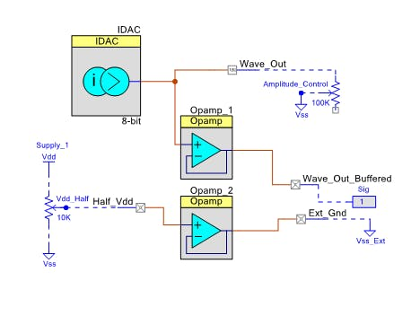 PSoC internal IDAC and Opamp
That's why higher frequency is achieved by skipping values which will increase the stepping noise (harmonics component).
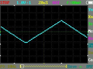 1 / 2 • Triangular Waveform with DDS (see those steps?)
This image is showing the visible steps in a triangular wave. It can be improved by passing the signal through Low Pass Filter. An automatic LPF will be implemented inside PSoC using Analog Multiplexer and an external capacitor.
For user input 3, 100 k pot and 2 push switches are used. One of the pot is connected to ADC. CPU reads ADC value at the end of each wave cycle and adjust output signal frequency by varying delay. This pot will allow fine tuning the frequency.
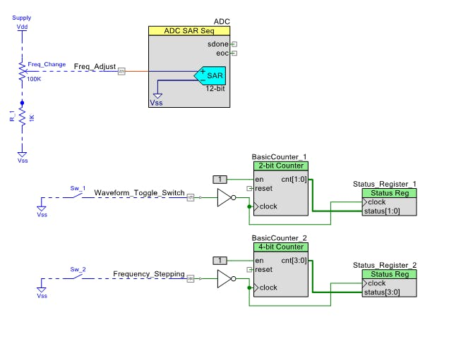 ADC for frequency control
The second pot will control gain/amplitude of output waveform by changing the IDAC load. Vp-p can be any value between 100mV to 4900 mV.
The third pot is connected to the input of the second internal Opamp of PSoC 4 which can output almost any fixed DC voltage between Vcc and Gnd. This signal can be used as external ground for the signal, which will allow offset capability.
One of the push switch will toggle between Sine/Square/Triangular/Saw wave and the other will be used for frequency stepping ( increasing/decreasing in larger steps)
Step 2: Building Test Prototype
After understanding the working principle, it's time for a quick breadboard prototyping with a beta firmware. And it worked!
 Prototyping on breadboard
Step 2: Building the Hardware
Once the concept is verified from prototyping, it's time to build a permanent solution.
- First, all components are neatly placed on a prototyping borad
- Next, interconnections between components and the PSoC is made with 0 ohms link resistors and insulated wire
- Finally, soldering all the points complete the circuit.
 1 / 3 • Soldering components
Step 3: Programming with PSoC Creator
PSoC Creator 4.2 is used to configure the internal hardware. First bootloader component is configured.
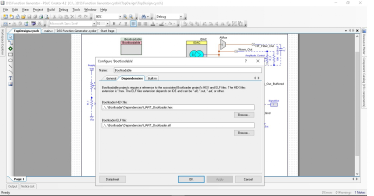 Bootloader is required for Cy8C049 kit
Next, ADC, IDAC, Opamps, AMux components are dragged and dropped from component catalog and interconnected with virtual wires. Since, this is a System on Chip, so after compilation these components will wire up internally with programmable data paths!
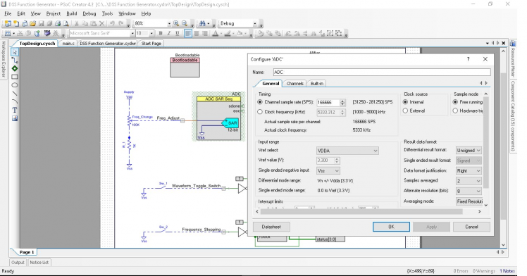 1 / 3 • Configuring ADC
The internal system clock (IMO) is set to run the CPU @ 48 MHz to reduce code execution time which has direct impact on output frequency.
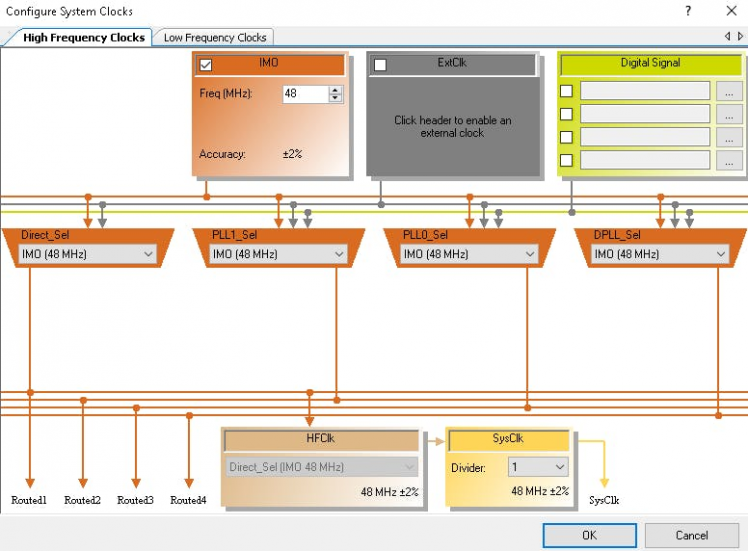 Setting up system clock 48 MHz
Then, the C code is written for the ARM Cortex M0 CPU.
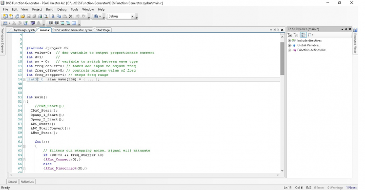 Code for MCU
Finally, code is compiled and uploaded to the kit.
Check these tutorial for details.
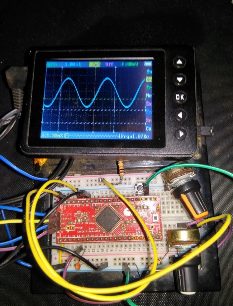
Step 4: Viewing Waveforms on a DSO
Now, we have a fully functional function generator (no pun) ! Check the following video for device operation.
Operation of Function Generator (sorry for the glitches due to loose USB power)Limitations
The device is good for hobby and educational purpose but not good for professional works. There are some limitations that may turn this device useless for some applications..
- No Duty Cycle Control
- DDS does not produce Smooth Analog waveform
- Wave Shape Distortion at Higher frequency due to step skipping
- HF Filtering Attenuates Signal
- Only 10 mA Load Driving Capability limited by Internal Opamps
- Frequency Stability depends on ADC Conversion Accuracy
- Maximum Amplitude limited by Vcc ( 1.8 -5.5 V)
- Amplitude Clipping by 0.7V near Vcc due to Opamp
- Non Linear Frequency Sweep and Stepping
- CPU is always busy due to linear coding scheme
Although, some of these limitation can be improved by adding additional hardware and developing better firmware.

Leave your feedback...