
Lora Powered Solar Pv Monitoring System With Blues &qubitro

Made by pradeeplogu0
About the project
Will guide you to build a LoRa E5-powered solar PV monitoring system with Blues cellular IoT and Qubitro cloud.
Project info
Difficulty: Moderate
Platforms: Adafruit, DFRobot, Seeed Studio, Blues Wireless
Estimated time: 1 day
License: GNU General Public License, version 3 or later (GPL3+)
Items used in this project
Hardware components

Story
LoRa is a wireless network solution that emerged in the field of IoT. It is a low-power and wide-area network with low power consumption and a long transmission range. In this project, I’m going to explain how to build a LoRa-powered solar power monitoring system with the help of cellular IoT. The data from the photovoltaic solar panel is sensed and collected from sensors and transmitted using LoRa modules. Further, the data is uploaded to a Qubitro cloud portal via Blues Wireless cellular IoT notecards in the base station. Using Qubitro API we can monitor and analyze the solar PV system performance.
Hardware Requirements:
Software:
Flow Overview:
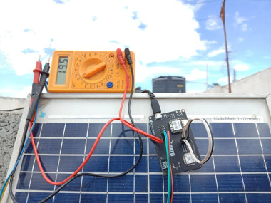
To monitor the solar PV cells, here I’m using a Gravity I2C Wattmeter sensor. Through this, we can monitor the generated voltage and consumed power and also the load current. Also, I need to monitor the solar light intensity and the temperature to analyze the generated voltage vs solar environment status. For this, I have used the BH1750 Light Intensity sensor and Grove Temperature and Humidity sensor.
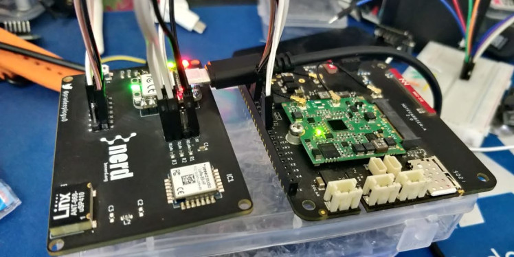
Now, we are ready with the sensing unit. Next, let’s design a system that can collect the sensor data and transfer it via LoRa. To design this system, I have used Seeedstudio Fusion PCB service. And they also offer a completely free PCB for your LoRa Wio E5 design. Here is the 3D image of my design.
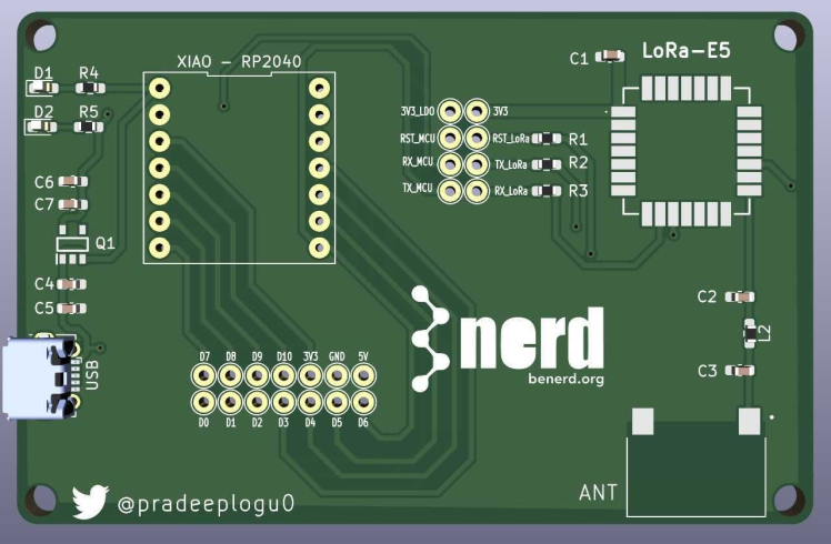
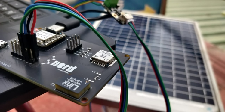
In this design, I have added Xiao RP2040 with LoRa E5.
Now, we can connect all those sensors with Xiao RP2040 and transfer them via LoRa E5. That’s all about the sender node. Next, we have to build a receiver to receive the data from our sender node and then publish it to the cloud. Here I'm also going to use the same PCB design with Blues Notecardand Notecarriers. Xiao +LoRa E5 PCB will receive the data from the sender, and it will transfer the data via Blues Cellular Notecard.

Finally, we can use Qubitro and Qubitro API to share and visualize our solar PV data.
Hardware Connection:

On the transmitter side connect all three sensors with the XIAO RP2040 by using the I2C port. And the Wio E5 is already connected to the Xiao RP2040 by using the UART port.
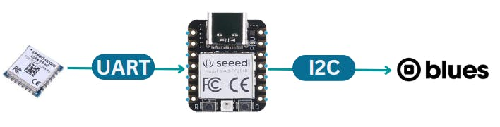
On the receiver side connect the Blues Wireless notecard with the XIAO RP2040 using the I2C port. And the Wio E5 is already connected by using the UART port. The receiver node will receive the data via LoRa and transfer the data to the cloud by using the Blues Notecard.
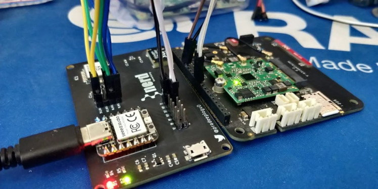
Let’s Bring Up the Board First:
Seeed Studio also offers free functional testing of your PCB boards. For my design, I have also done a base functional test to check my board is fine. In my design, I have added a Wio E5 with Xiao RP2040 by using the UART lines. And we can easily communicate with the Wio E5 using AT commands. So, if my Wio E5 responds to our AT commands, it means all good. It means technically “I’m alive ''. On the production site, we can’t use the serial monitor to check the PCB's response, so I have planned to implement some LEDs on it. But luckily the Xiao RP2040 has an onboard RGB led. We can directly use that to do our functional testing. Here is my simple Arduino sketch.
#include <Adafruit_NeoPixel.h>

int Power = 11;
int PIN  = 12;
#define NUMPIXELS 1

Adafruit_NeoPixel pixels(NUMPIXELS, PIN, NEO_GRB + NEO_KHZ800);

static char recv_buf[512];

int counter = 0;

static int at_send_check_response(char *p_ack, int timeout_ms, char *p_cmd, ...)
{
  int ch;
  int num = 0;
  int index = 0;
  int startMillis = 0;
  va_list args;
  memset(recv_buf, 0, sizeof(recv_buf));
  va_start(args, p_cmd);
  Serial1.print(p_cmd);
  Serial.print(p_cmd);
  va_end(args);
  delay(200);
  startMillis = millis();

if (p_ack == NULL)
return 0;

  do
  {
while (Serial1.available() > 0)
    {
      ch = Serial1.read();
      recv_buf[index++] = ch;
      Serial.print((char)ch);
      delay(2);
    }

if (strstr(recv_buf, p_ack) != NULL)
    pixels.clear();
    pixels.setPixelColor(0, pixels.Color(0, 5, 0));
    pixels.show();
    delay(500);
  }
else {

    Serial.println("Send failed!rnrn");
    pixels.clear();
    pixels.setPixelColor(0, pixels.Color(5, 0, 0));
    pixels.show();
    delay(500);
  }
  digitalWrite(LED_BUILTIN, LOW);    // turn the LED off by making the voltage LOW
  delay(1000);
}
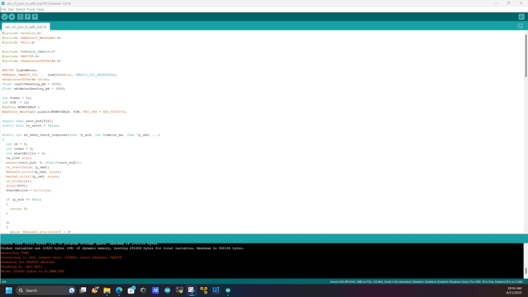
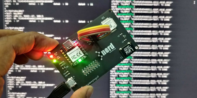
This will send and receive the AT command and response from the Wio E5. If we get the correct response the LED will glow in green, if not it will glow in red. Here is my board response for my functional test script.
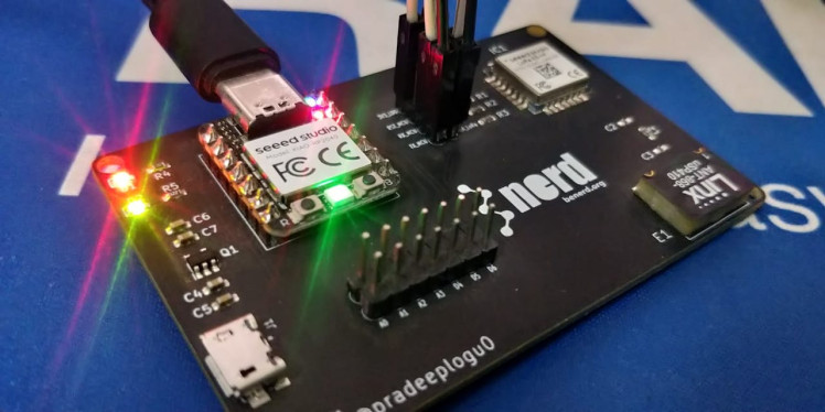
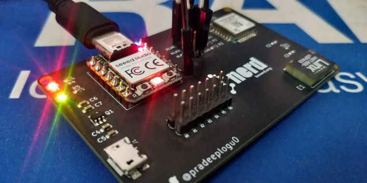
It gives me a green led which means my PCB is good to go. I just tried to disconnect the pin from the LoRa E5. Here is the board's response.
Now let's set up our transmitter and receiver nodes to send and receive data via LoRa.
P2P Communication BW Nodes:
So, now we know our PCBs are working as well. As a second phase of this functional testing. Let's try to send and receive some data packets between the boards via the LoRa E5 modules.
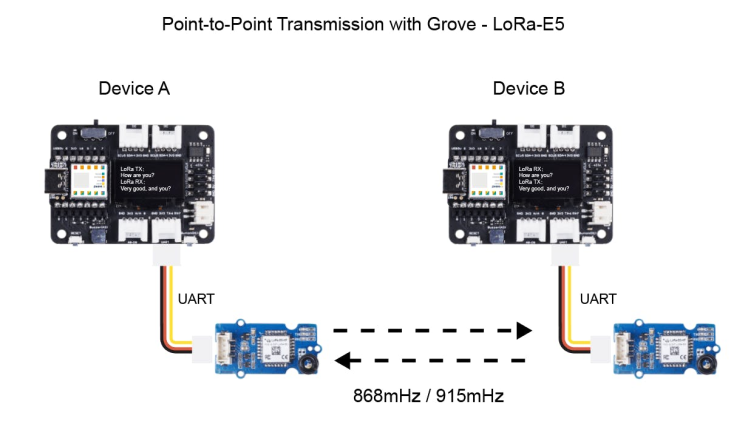
I'm using this Seeed Studios LoRa Wio E5s P2P example. Here are the demo transmitter and receiver codes. Just upload these codes to the Xiao boards then wait to see the results.
# include <Arduino.h>
#define NODE_SLAVE //Enable for Slave //Comment for Master
static char recv_buf[512];
static bool is_exist = false;
static int at_send_check_response(char *p_ack, int timeout_ms, char*p_cmd, ...)
{
  int ch = 0;
  int index = 0;
  int startMillis = 0;
  va_list args;
  memset(recv_buf, 0, sizeof(recv_buf));
  va_start(args, p_cmd);
  Serial1.printf(p_cmd, args);
  Serial.printf(p_cmd, args);
  va_end(args);
  delay(200);
  startMillis = millis();
  if (p_ack == NULL)
  {
    return 0;
  }
  do
  {
    while (Serial1.available() > 0)
    {
      ch = Serial1.read();
      recv_buf[index++] = ch;
      Serial.print((char)ch);
      delay(2);
    }
    if (strstr(recv_buf, p_ack) != NULL)
    {
      return 1;
    }
  } while (millis() - startMillis < timeout_ms);
  return 0;
}
static int recv_prase(void)
{
  char ch;
  int index = 0;
  memset(recv_buf, 0, sizeof(recv_buf));
  while (Serial1.available() > 0)
  {
    ch = Serial1.read();
    recv_buf[index++] = ch;
    Serial.print((char)ch);
    delay(2);
  }
  if (index)
  {
    char *p_start = NULL;
    char data[32] = {
      0,
    };
    int rssi = 0;
    int snr = 0;
    p_start = strstr(recv_buf, "+TEST: RX "5345454544");
    if (p_start)
    {
      p_start = strstr(recv_buf, "5345454544");
      if (p_start && (1 == sscanf(p_start, "5345454544%s", data)))
      {
        data[4] = 0;
        Serial.print(data);
        Serial.print("rn");
      }
      p_start = strstr(recv_buf, "RSSI:");
      if (p_start && (1 == sscanf(p_start, "RSSI:%d,", &rssi)))
      {
      }
      p_start = strstr(recv_buf, "SNR:");
      if (p_start && (1 == sscanf(p_start, "SNR:%d", &snr)))
      {
      }
      return 1;
    }
  }
  return 0;
}
static int node_recv(uint32_t timeout_ms)
{
  at_send_check_response("+TEST: RXLRPKT", 1000, "AT+TEST=RXLRPKTrn");
  int startMillis = millis();
  do
  {
    if (recv_prase())
    {
      return 1;
    }
  } while (millis() - startMillis < timeout_ms);
  return 0;
}
static int node_send(void)
{
  static uint16_t count = 0;
  int ret = 0;
  char data[32];
  char cmd[128];
  memset(data, 0, sizeof(data));
  sprintf(data, "%04X", count);
  sprintf(cmd, "AT+TEST=TXLRPKT,"5345454544%s"rn", data);
  ret = at_send_check_response("TX DONE", 2000, cmd);
  if (ret == 1)
  {
    count++;
    Serial.print("Sent successfully!rn");
  }
  else
  {
    Serial.print("Send failed!rn");
  }
  return ret;
}
static void node_recv_then_send(uint32_t timeout)
{
  int ret = 0;
  ret = node_recv(timeout);
  delay(100);
  if (!ret)
  {
    Serial.print("rn");
    return;
  }
  node_send();
  Serial.print("rn");
}
static void node_send_then_recv(uint32_t timeout)
{
  int ret = 0;
  ret = node_send();
  if (!ret)
  {
    Serial.print("rn");
    return;
  }
  if (!node_recv(timeout))
  {
    Serial.print("recv timeout!rn");
  }
  Serial.print("rn");
}
void setup(void)
{
  Serial.begin(115200);
  // while (!Serial);
  Serial1.begin(9600);
  Serial.print("ping pong communication!rn");
  if (at_send_check_response("+AT: OK", 100, "ATrn"))
  {
    is_exist = true;
    at_send_check_response("+MODE: TEST", 1000, "AT+MODE=TESTrn");
    at_send_check_response("+TEST: RFCFG", 1000, "AT+TEST=RFCFG,866,SF12,125,12,15,14,ON,OFF,OFFrn");
    delay(200);
  }
  else
  {
    is_exist = false;
    Serial.print("No E5 module found.rn");
  }
}
void loop(void)
{
  if (is_exist)
  {
# ifdef NODE_SLAVE
    node_recv_then_send(2000);
# else
    node_send_then_recv(2000);
    delay(3000);
# endif
  }
}
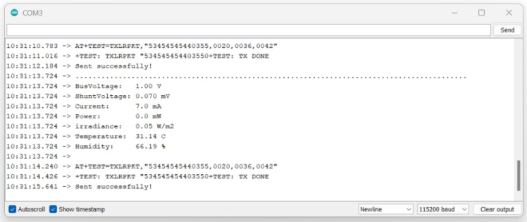
If you get this kind of response means you are good, we are good to go.
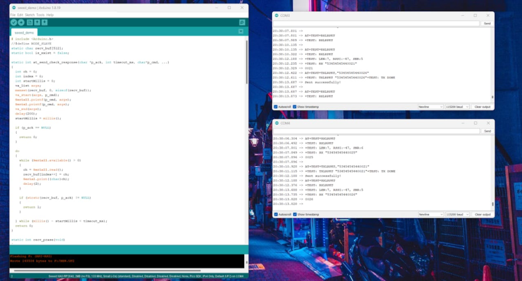
In this image, you can see these two boards are showing some transmitting/ receiving data.
Transmitter Node Setup:
To monitor the generated and consumed solar energy we are going to use the DFRobot’s gravity I2C Watt meter sensor. This can easily measure the voltage and current and then transfer the data via the I2C protocol.
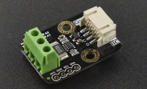
As I mentioned this Watt meter sensor will work on the I2C protocol and we can even configure this up to 4 different addresses as per our needs. In this tutorial, I’m going to use the default address. Use this guide to learn more about the Wattmeter.

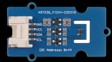
Next, the BH1750 is a calibrated digital light sensor IC that measures the incident light intensity and converts it into a 16-bit digital number. The BH1750I sensor directly gives digital output. The sensor output can be accessed through an I2C interface. It can measure ambient light intensity and the measurement unit is Lux. Interfacing this module with our transmitter is quite easy since it is an I2C sensor. So, now we can easily correlate the light vs generated energy.
Next, we have to measure the temperature in the solar PV area. For that, we can use the Grove Temp Humi sensor (SHT40); this one is also an I2C sensor. So, the connection is also quite simple. We just need SCL and SDA. Use this guide to learn more about the Grove Temp Humi sensor (SHT40).
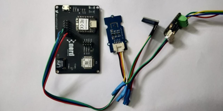
Now we have all our sensors ready, just connect them all and finally connect to our Xiao RP2040.
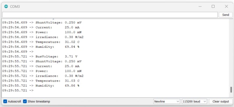
Here is the Arduino sketch which can collect all the data from the three different sensors, and it will print out in the serial monitor.
#include <Wire.h>
#include "DFRobot_INA219.h"
#include <BH1750.h>
#include <SensirionI2CSht4x.h>

BH1750 lightMeter;
DFRobot_INA219_IIC     ina219(&Wire, INA219_I2C_ADDRESS1);
SensirionI2CSht4x sht4x;
float ina219Reading_mA = 1000;
float extMeterReading_mA = 1000;

void setup(void)
{
  Serial.begin(115200);
  while (!Serial);

  Serial.println();
  while (ina219.begin() != true) {
    Serial.println("INA219 begin faild");
    delay(2000);
  }

  lightMeter.begin();
  Serial.println(F("BH1750 Test begin"));
  ina219.linearCalibrate(ina219Reading_mA, extMeterReading_mA);
  Serial.println();

  uint16_t error;
  char errorMessage[256];

  sht4x.begin(Wire);

  uint32_t serialNumber;
  error = sht4x.serialNumber(serialNumber);
  if (error) {
    Serial.print("Error trying to execute serialNumber(): ");
    errorToString(error, errorMessage, 256);
    Serial.println(errorMessage);
  } else {
    Serial.print("Serial Number: ");
    Serial.println(serialNumber);
  }
}

void loop(void)
{
  Serial.print("BusVoltage:   ");
  Serial.print(ina219.getBusVoltage_V(), 2);
  Serial.println("V");
  Serial.print("ShuntVoltage: ");
  Serial.print(ina219.getShuntVoltage_mV(), 3);
  Serial.println("mV");
  Serial.print("Current:      ");
  Serial.print(ina219.getCurrent_mA(), 1);
  Serial.println("mA");
  Serial.print("Power:        ");
  Serial.print(ina219.getPower_mW(), 1);
  Serial.println("mW");

  float lux = lightMeter.readLightLevel();
  float irr = (lux * 0.0079);
  Serial.print("irradiance:   ");
  Serial.print(irr);
  Serial.println(" W/m2");

  uint16_t error;
  char errorMessage[256];

  float temperature;
  float humidity;
  error = sht4x.measureHighPrecision(temperature, humidity);
  if (error) {
    Serial.print("Error trying to execute measureHighPrecision(): ");
    errorToString(error, errorMessage, 256);
    Serial.println(errorMessage);
  } else {
    Serial.print("Temperature:  ");
    Serial.println(temperature);
    Serial.print("Humidity:     ");
    Serial.println(humidity);
  }
  Serial.println("");
  delay(1000);
}
By using this sketch, we can collect the sensor data.
Now we have to add these sensor data in LoRa transmission. For that process use the following code. This will transmit the sensor's data as encoded LoRa packets.
Upload the above Arduino code to the board and wait for the serial monitor results.
Receiver Node Setup:
To receive the data via LoRa protocol we are going to use the same kind of PCB but in this, we have added the Blues Notcardvia the I2C pin of the Xiao RP2040.
This allows us to reach LoRa data to the cloud. Just use the following sketch to test the Notecard response with the Xiao RP2040.
#include <Arduino.h>
#include <Notecard.h>
#include <Wire.h>

#define PRODUCT_UID "com.gmail.pradeeplogu26:cold_storage_monitor"    // "com.my-company.my-name:my-project"

#define myProductID PRODUCT_UID
Notecard notecard;

#include <Adafruit_NeoPixel.h>

int Power = 11;
int PIN  = 12;
#define NUMPIXELS 1
Adafruit_NeoPixel pixels(NUMPIXELS, PIN, NEO_GRB + NEO_KHZ800);

static char recv_buf[512];
static bool is_exist = false;

static int at_send_check_response(char *p_ack, int timeout_ms, char *p_cmd, ...)
{
  int ch = 0;
  int index = 0;
  int startMillis = 0;
  va_list args;
  memset(recv_buf, 0, sizeof(recv_buf));
  va_start(args, p_cmd);
  Serial1.printf(p_cmd, args);
  Serial.printf(p_cmd, args);
  va_end(args);
  delay(200);
  startMillis = millis();

  if (p_ack == NULL)
  {
    return 0;
  }

  do
  {
    while (Serial1.available() > 0)
    {
      ch = Serial1.read();
      recv_buf[index++] = ch;
      Serial.print((char)ch);
      delay(2);
    }

    if (strstr(recv_buf, p_ack) != NULL)
    {
      return 1;
    }

  } while (millis() - startMillis < timeout_ms);
  return 0;
}

static int recv_prase(void)
{
  char ch;
  int index = 0;
  memset(recv_buf, 0, sizeof(recv_buf));
  while (Serial1.available() > 0)
  {
    ch = Serial1.read();
    recv_buf[index++] = ch;
    Serial.print((char)ch);
    delay(2);
  }

  if (index)
  {
    char *p_start = NULL;
    char data[32] = {
      0,
    };
    int rssi = 0;
    int snr = 0;

    p_start = strstr(recv_buf, "+TEST: RX "5345454544");
    if (p_start)
    {
      p_start = strstr(recv_buf, "5345454544");
      if (p_start && (1 == sscanf(p_start, "5345454544%s,", data)))
      {
        data[16] = 0;
        int tvoc;
        int co2;
        int temp;
        int humi;
        char *endptr;
        char *endptr1;
        char *endptr2;
        char *endptr3;
        char datatvoc[5] = {data[0], data[1], data[2], data[3]};
        char dataco2[5] = {data[4], data[5], data[6], data[7]};
        char datatemp[5] = {data[8], data[9], data[10], data[11]};
        char datahumi[5] = {data[12], data[13], data[14], data[15]};

        tvoc = strtol(datatvoc, &endptr, 16);
        co2 = strtol(dataco2, &endptr1, 16);
        temp = strtol(datatemp, &endptr, 16);
        humi = strtol(datahumi, &endptr1, 16);


        double temperature = 0;
        J *rsp = notecard.requestAndResponse(notecard.newRequest("card.temp"));
        if (rsp != NULL) {
          temperature = JGetNumber(rsp, "value");
          notecard.deleteResponse(rsp);
        }

        double voltage = 0;
        rsp = notecard.requestAndResponse(notecard.newRequest("card.voltage"));
        if (rsp != NULL) {
          voltage = JGetNumber(rsp, "value");
          notecard.deleteResponse(rsp);
        }

        J *req = notecard.newRequest("note.add");
        if (req != NULL) {
          JAddBoolToObject(req, "sync", true);
          J *body = JCreateObject();
          if (body != NULL) {
            JAddNumberToObject(body, "temp-note", temperature);
            JAddNumberToObject(body, "voltage", voltage);
            JAddNumberToObject(body, "temp", temperature );
            JAddNumberToObject(body, "humi", co2);
            JAddNumberToObject(body, "bus_v", temp);
            JAddNumberToObject(body, "shu_v", humi);
            JAddNumberToObject(body, "current", co2);
            JAddNumberToObject(body, "powerr", temp);
            JAddNumberToObject(body, "irr", humi);
            JAddItemToObject(req, "body", body);

          }
          notecard.sendRequest(req);
          Serial.println("NoteCard Data Sent");
        }
      }

      p_start = strstr(recv_buf, "RSSI:");
      if (p_start && (1 == sscanf(p_start, "RSSI:%d,", &rssi)))
      {
        String newrssi = String(rssi);

        Serial.print(rssi);
        Serial.print("rn");

      }
      p_start = strstr(recv_buf, "SNR:");
      if (p_start && (1 == sscanf(p_start, "SNR:%d", &snr)))
      {
        Serial.print(snr);
        Serial.print("rn");


      }
      return 1;
    }
  }
  return 0;
}

static int node_recv(uint32_t timeout_ms)
{
  at_send_check_response("+TEST: RXLRPKT", 1000, "AT+TEST=RXLRPKTrn");
  int startMillis = millis();
  do
  {
    if (recv_prase())
    {
      return 1;
    }
  } while (millis() - startMillis < timeout_ms);
  return 0;
}

void setup()
{

  Wire.begin();
  notecard.begin();

  J *req = notecard.newRequest("hub.set");
  if (myProductID[0]) {
    JAddStringToObject(req, "product", myProductID);
  }
  JAddStringToObject(req, "mode", "continuous");

  notecard.sendRequest(req);


  Serial.begin(115200);
  Serial1.begin(9600);
  Serial.print("Receiverrn");

  if (at_send_check_response("+AT: OK", 100, "ATrn"))
  {
    is_exist = true;
    at_send_check_response("+MODE: TEST", 1000, "AT+MODE=TESTrn");
    at_send_check_response("+TEST: RFCFG", 1000, "AT+TEST=RFCFG,868,SF12,125,12,15,14,ON,OFF,OFFrn");
    delay(200);
  }
  else
  {
    is_exist = false;
    Serial.print("No Serial1 module found.rn");

  }

  pixels.begin();
  pinMode(Power, OUTPUT);
  pinMode(LED_BUILTIN, OUTPUT);
  digitalWrite(Power, HIGH);
  delay(200);
}


void loop()
{
  if (is_exist)
  {
    digitalWrite(LED_BUILTIN, HIGH);   // turn the LED on (HIGH is the voltage level)
    pixels.clear();
    pixels.setPixelColor(0, pixels.Color(0, 5, 0));
    pixels.show();
    delay(500);

    node_recv(2000);

    digitalWrite(LED_BUILTIN, LOW);    // turn the LED off by making the voltage LOW
    pixels.clear();
    pixels.setPixelColor(0, pixels.Color(5, 0, 0));
    pixels.show();
    delay(500);

  }

}
And if you want to know more about the Blues Wireless Notecard just watch this great YouTube tutorial.
Now we are good at deploying the receiver, just go to the Notehub and create a new project.
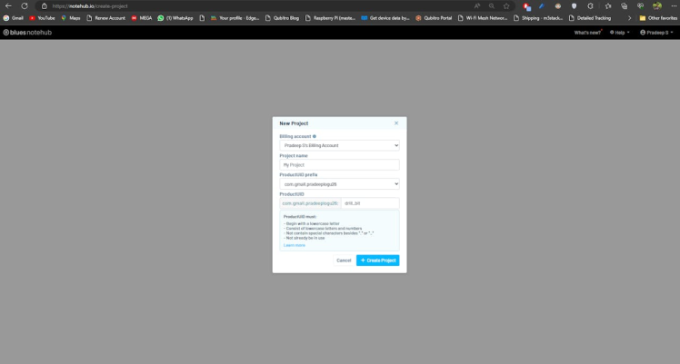
Note: You have to change the Product ID name in the sketch.
Then upload the following sketch to decode the LoRa data and then it will revert the data to Notehubvia Blues Notecard. Then just look at the serial monitor results; it will show you the received and decoded data.
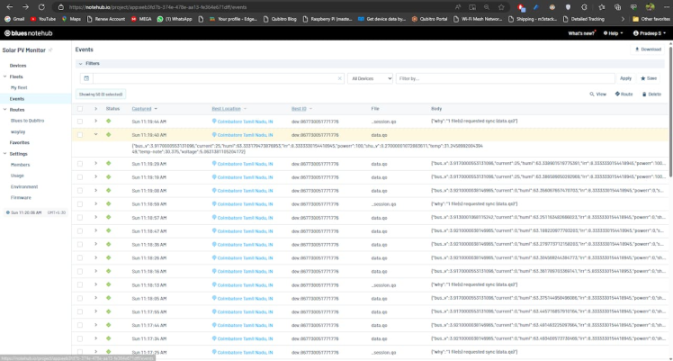
Just navigate to the Blues Notehuband wait for the response from the receiver.
The next step is to route the Notehub data to an external cloud platform.
Data Routing
First, let's connect Qubitro with Notehub. Go to the Qubitro portal and create a new MQTT-based connection.
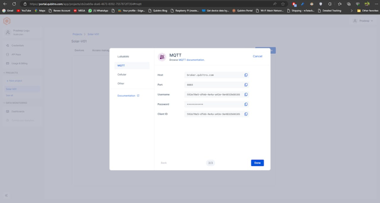
Then copy the credentials, next open the Notehub and navigate to the routes page.
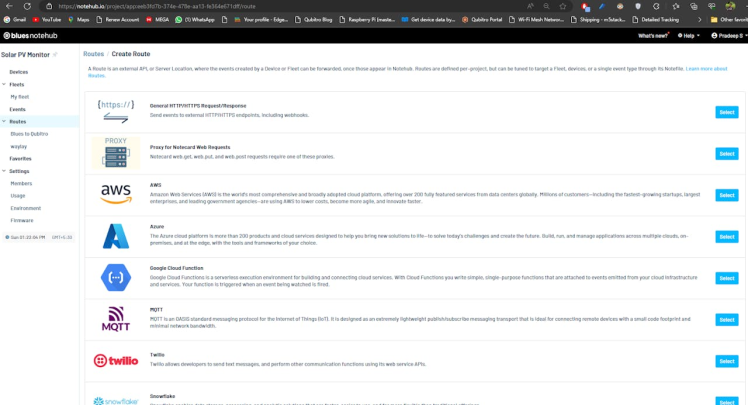
Create a new MQTT route and insert your Qubitro credentials.
Note: In Qubitro MQTT topic is MQTT username.
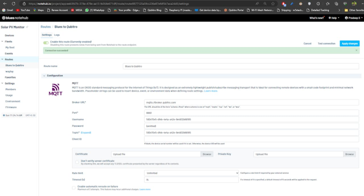
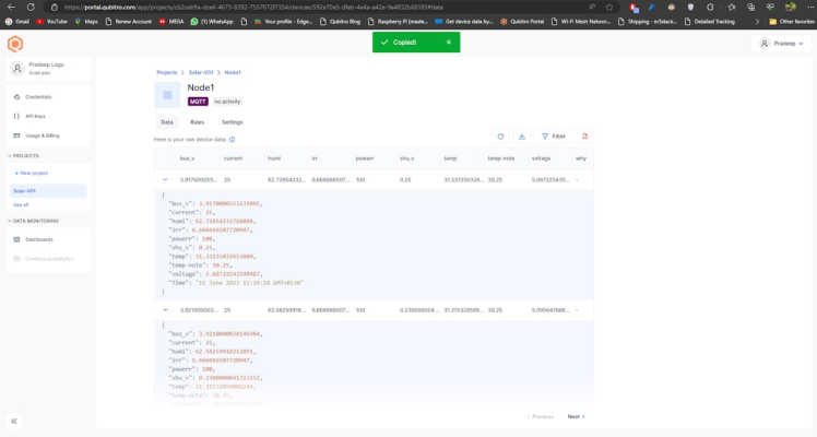
Next, set the data as body only. If you want to get more information about receivers like location, temp. Use this Blues JSONguide to learn more about it.

Check back the Qubitro portal and look for the incoming data.
Now let's add some notification systems that can alert us if anything unusual exists.
Alert Management:
Navigate to the rules page in the Qubitro Portal and create a new rule.
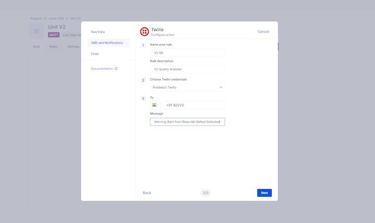
Once the rule logic is true, it will auto-trigger the service. So, now we have finished the alert system. Next, I will make a website that can show our data in Realtime 24/7.
Live Data Visualization:
To visualize our sensor data in graphs and charts in the Qubitro dashboard.
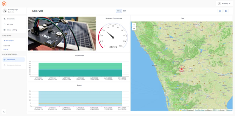
Also, you can set your dashboard to the public, so anyone can access it.

We have reached the final and most crucial step. How can we share data with other users on a mobile app or web application? Qubitro enables APIs to share cloud data with various platforms and languages.
To test it out, go to the Credentials tab in the Qubitro portal and copy the API key.
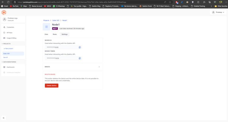
Then visit this URL https://qubitro-api.readme.io/reference/getdevice, which will require you to fill in some inputs.
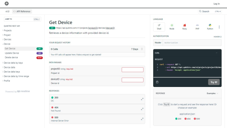
Enter the API key in the “Bearer-API Key” format, enter the Device ID and Project you used in the Qubitro Project setup, and then click on the “Try It” button. You can see your whole data from your Blues hardware.
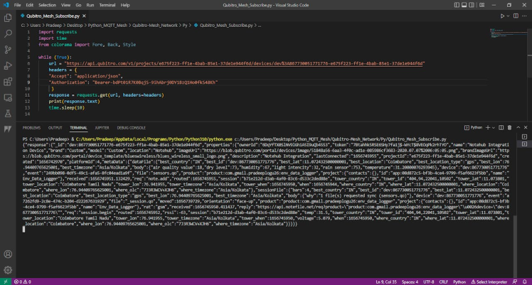
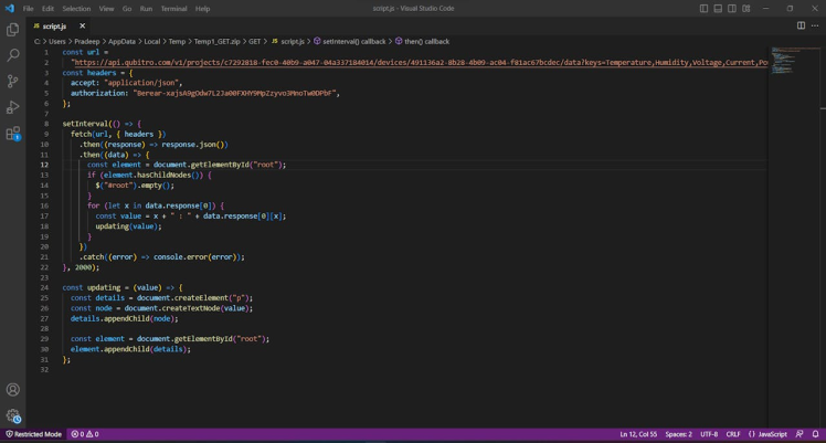
Let’s make a simple Python script to get the API response. Just copy the below Python script and change the keys, then execute.
import requests
import time
from colorama import Fore, Back, Style
while (True):
    URL = "https://api.qubitro.com/v1/projects/e675f223-ff1e-4bab-85e1-37de1e944f6d/de    vices/dev%3A867730051771776-e675f223-ff1e-4bab-85e1-37de1e944f6d"
    headers = {
    "Accept": "application/JSON",
    "Authorization": "Bearer-xxxxxxxxxxxxxxxxxxxxxxxx"
    }
    response = requests.get(URL, headers=headers)
    print(response. Text)
    time. Sleep(10)
It will return the data from the hardware.
So now you can share your PV data with the external world.
Live Website:
We have created our live website using HTML and Java Scripts. It can display real-time data on a public website.
Anyone can access it from anywhere on the internet.
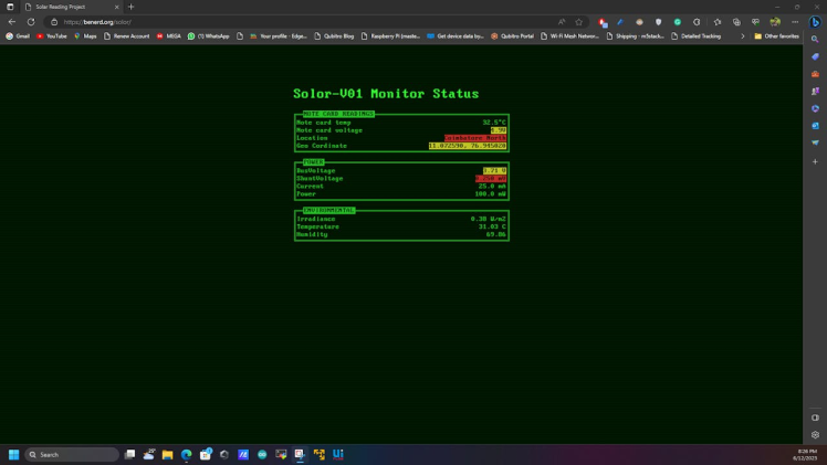
Use this URL to access the website: Solar Reading Project (benerd.org)
Conclusion:
Solar energy is a great option for alternative energy because it is environmentally friendly, cost-effective, and sustainable. However, we need to use it wisely to maximize its advantages. LoRa-powered systems can help us track and save our efforts. I hope you liked this project. I will be back with another exciting one soon. Thank you.
Credits
Related products


Leave your feedback...