
Light Brakes

Made by nickbild / Artificial intelligence / Augmented Reality / Wearables
About the project
Light Brakes are smart glasses that selectively filter out excessively bright spots from a wearer's field of vision.
Project info
Items used in this project

Story
Light Brakes
Light Brakes are smart glasses that selectively filter out excessively bright spots (e.g. the Sun, headlights, glare) from a wearer's field of vision in real-time. The remainder of the view is unobstructed and transparent.
How It Works
A pair of sunglasses (non-darkened glasses could also be used) are fitted with a camera to capture images of the wearer's field of vision. Captured images are processed in real-time to spatially locate areas of excessive brightness.
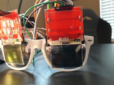
Graphic monochrome LCD displays have been disassembled and fitted in front of each lens in the glasses. The backing has been removed from the LCDs to render them transparent when no pixels are being displayed on them.
The locations of bright spots are translated into coordinates on the LCD displays, and pixel data is written to these coordinates to darken those regions. In this way, bright spots are blocked by the LCD pixels, while the rest of the view is clear and unobstructed.
Media
See it in action: YouTube
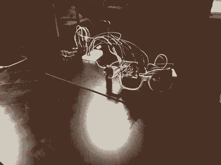
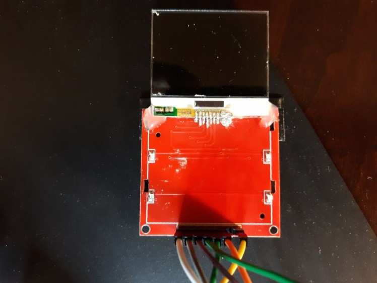
The glasses:
A close-up of the lenses:
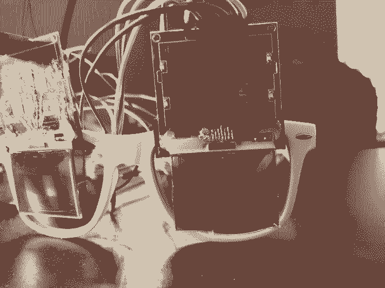
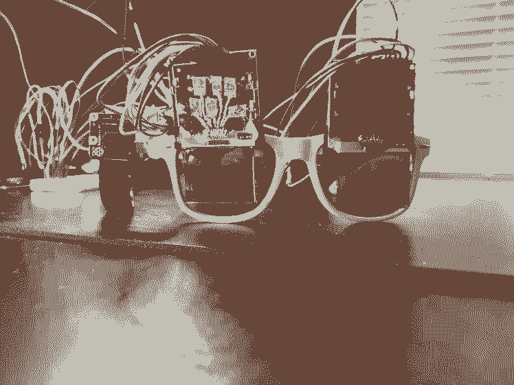
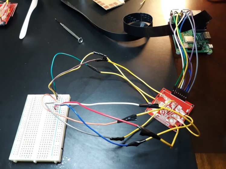
The full setup:
Software
To run the software, you'll need Python3 with the following modules installed:
Adafruit_Nokia_LCDAdafruit_GPIOpicameraPILimutilsskimagenumpycv2Then clone the repo:
git clone https://github.com/nickbild/light_brakes.git
Switch to the light_brakes directory, then run:
python3 bright_mask_pi.py
Bill of Materials
All parts can be acquired for ~$100.
- Raspberry Pi 3 B+ (or similar)
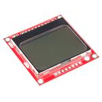
- 2 x Nokia 5110 LCDs
- Raspberry Pi Camera v2 (or similar)
- Sunglasses / Eyeglasses
- Conductive silver epoxy
- Hot glue and/or super glue
- Miscellaneous copper wires
How Not To Build A Device
Seeing a finished project can make it seem like the builder got a few parts together, hooked everything up, and voila -- a finished device!
Not so. It took a long, frustrating, string of failed attempts to get this working. In my case, I had a lot of trouble making electrical connections to the LCD after removing it from the breakout board.
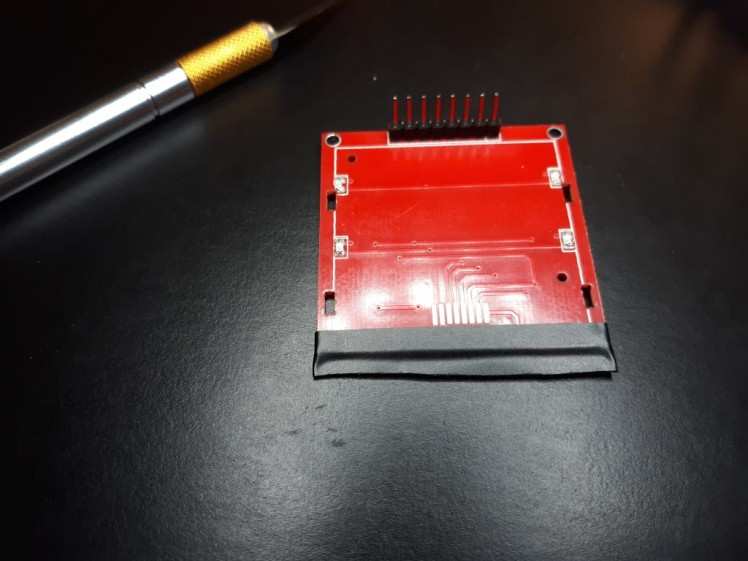
The pads on the LCD are connected to pads on the breakout board by a Zebra strip, and mechanical force by clamping. I needed to get the LCD off of the breakout board so that there is nothing behind it and it can be transparent.
These pads are too small for me to solder:
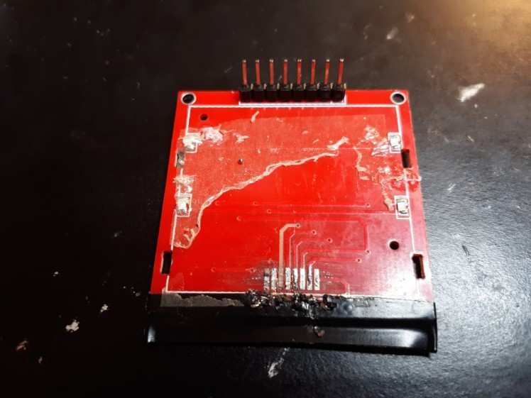
It's a nightmare of shorts and unsoldering adjacent pads whenever I solder a new pad; it invariably leads to something like this:
I imagine someone with more skill could handle this with little problem -- but I'm determined to build this device today. Not in months or years when my soldering skill (hopefully) improves.
And then, there is the LCD, with it's paper thin pads that are very close together on top of a glass plate. There's no way I can solder that. I'm not even sure it is solderable.
I tried a number of monstrosities, such as this:
I used copper tape to create fine traces from the pads to larger pads (something I can work with!) that I created. This was flaky because such fine strips of tape would not maintain contact with the substrate over time. I tried to improve the contact by putting a strip of z-axis tape between the pads and copper tape. It helped, but still flaky.
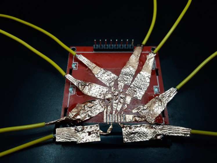
I decided I'd try to use conductive silver epoxy, and it was a huge improvement. It stays put and makes highly conductive connections. So I built the next slightly-less monstrous monstrosity:
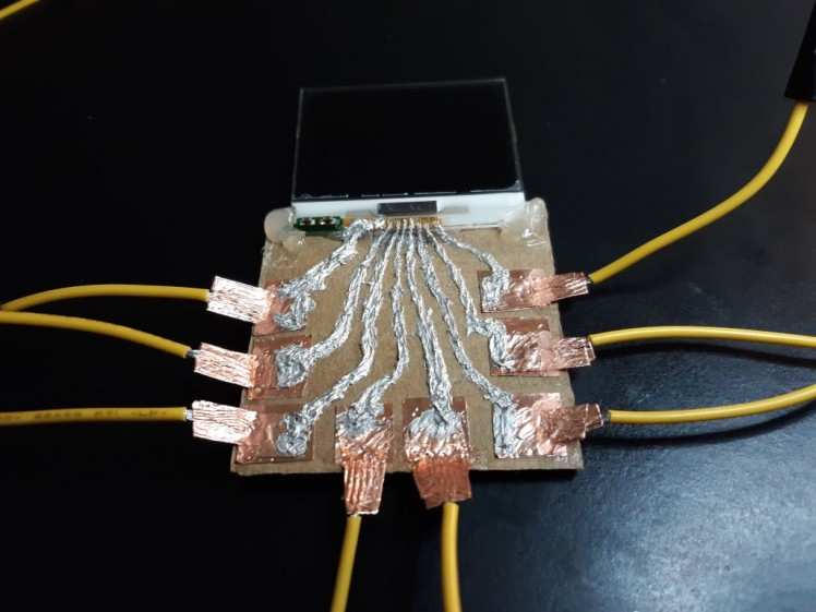
Frustratingly, when I powered it up -- nothing. My multimeter showed continuity and no shorts. My logic analyzer showed the right signals on all the lines. Something in all this complexity is going wrong that's beyond my ability to detect. I need a simpler solution, so I came up with this:
Some hot glue to hold the LCD to the board, and short stretches of silver epoxy to connect the pads. It was still a challenge to keep the traces isolated from one another, but it was doable with patience.
It took me weeks to get here, but finally, it works! This is not an exhaustive list of all my failures by any stretch of the imagination. There were the flat flexible cables, the solder paste, and the clamped wires held in place with mechanical force -- too painful to recount it all!
Future Direction
I would like to miniaturize the device by embedding the camera and processing in the frames of the glasses. I would also like to embed the LCD display directly into the lenses.
It has not escaped my notice that LCDs embedded in lenses could also be used to present information to the wearer, in addition to blocking bright light.
Words of Caution
Liquid crystals are toxic. If you break open the screen during disassembly, you may be exposed to this toxic material. Take appropriate precautions.
This is a prototype and not yet ready for the consumer market. If you build your own, you may find that your entire field of vision becomes unexpectedly blocked for a time resulting in a potentially dangerous situation. No guarantees are given regarding the UV blocking of Light Brakes. Don't stare at the sun. Use at your own risk.
About the Author
Credits
Related products


Leave your feedback...