
LED With Arduino 101

Made by electrouser1623
About the project
Learn how to light a LEDs using Digital Write and AnalogWrite on Arduino 101!
Project info
Items used in this project
Hardware components


Story
Introduction
Learn how to light a LEDs using Digital Write and AnalogWrite on Arduino 101!
One of the popular Arduino Basics is how to blink a LED.
So if you are a beginner, you're at the right place!
As you learn this basic, you get to understand how to program in Arduino IDEand how Arduino pins and PWM or Pulse Width Modulation works.
Understand LED specification, importance of resistors and basic bread-boarding.
Excited to be a LED rockstar? Lets start!
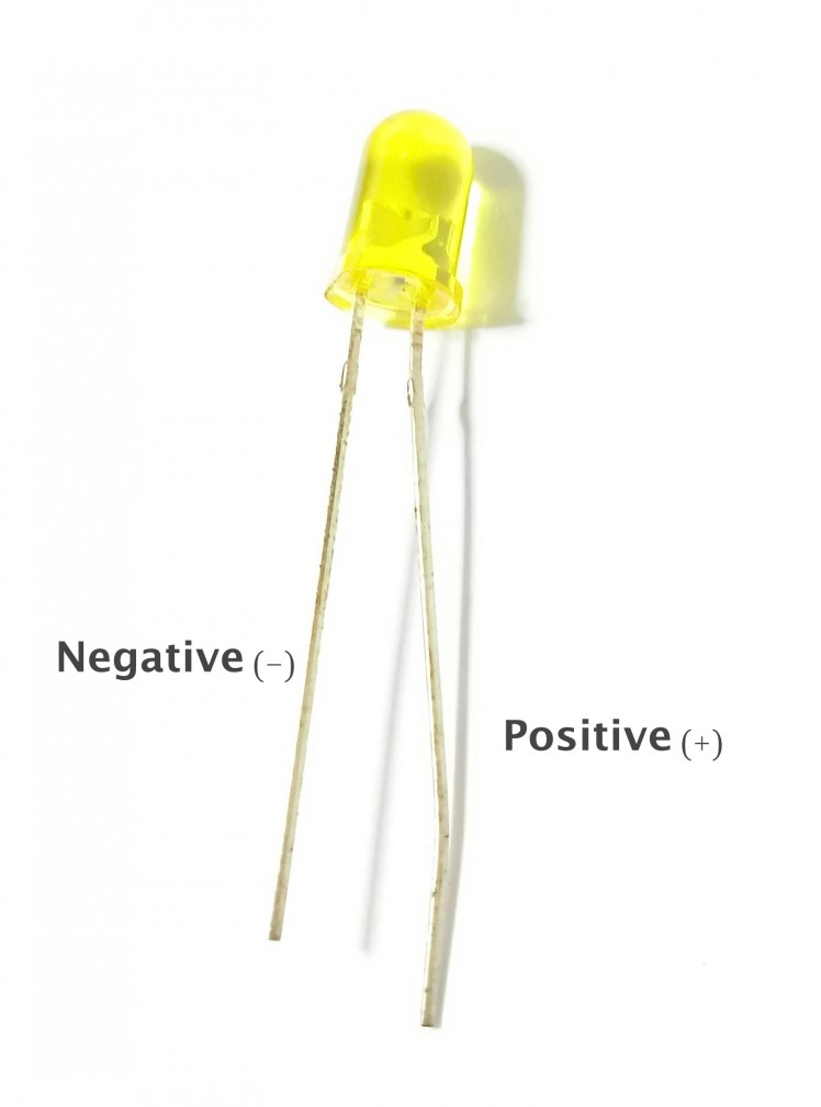
Know What a LED Is
Light Emitting Diode or LED is basically a Diode that can emit light.
Being a diode means it has Cathode pin, the negatively charged electrode by which electrons enter an electrical device, and Anode pin, positively chargedelectrode by which the electrons leave a device.
Grab a LED and look!. One long leg and one short. The long leg is Positve (Ano). The short leg is the Cathode.
Same length? No problem mate! Look inside the LED, largest metal is negative and smallest goes to Anode pin
; ; 1 / 2
1 / 2
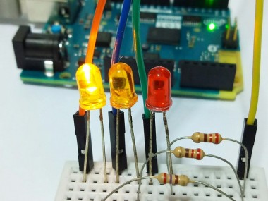
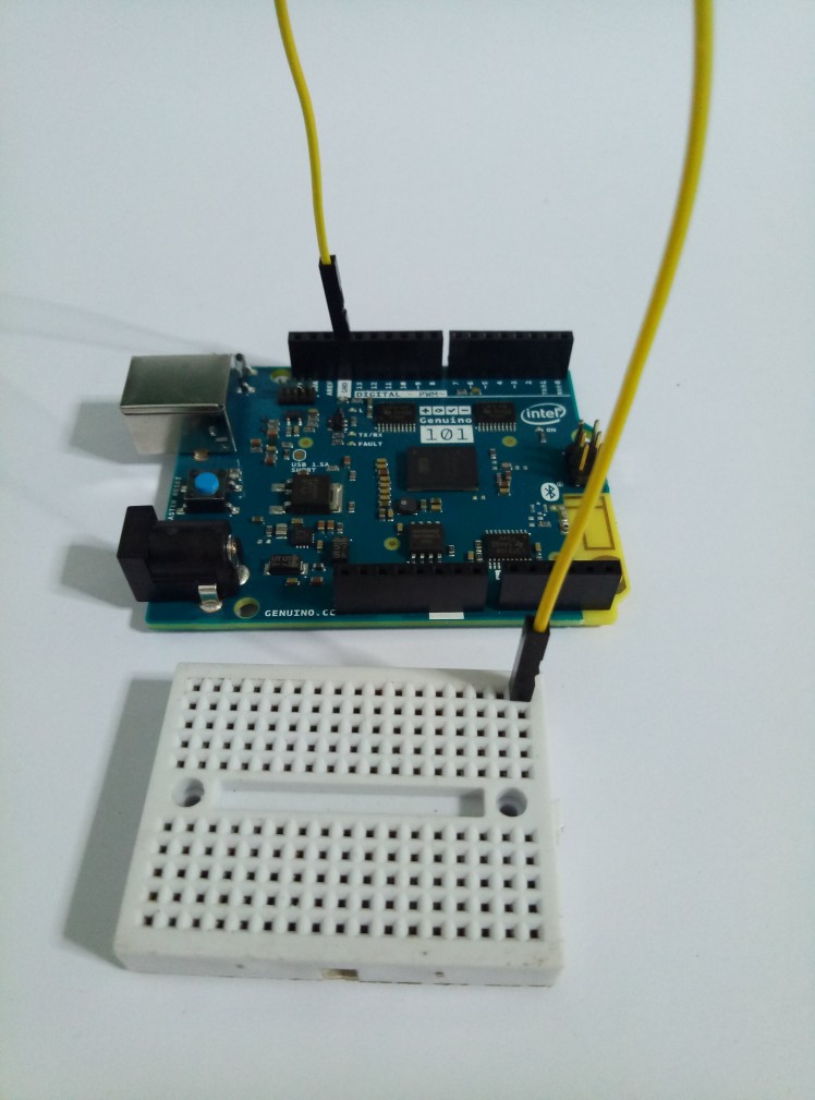
Build Our Circuit
I used a mini bread board. It has a big divider or horizontal lines in the middle that divides the connection of pins from top and bottom. All pins from the top are connected to each of its column. Same goes to the bottom.
Connect Arduino 101 pin GND (ground) to one of the bread board pins. I picked the upper left pin.
- Add 1 resistor to the bread board and one pin is connected to the jumper wire (on the same column). This means that our resistor is also connected to the ground.
- Insert the negative led of our led to the other end of resistor (on the same column) and its positive leg to ther column.
- Lastly, connect a jumper wire from Arduino 101 pin 13 to the column where the LED positive leg is connected.
Summarizing our circuit,
- the LED and resistor is in series of each other, this means that they are connected like a chain
- LED's positive leg is connected to digital pin 13
- LED's negative leg is connected to ground
Our resistor will help us to decrease the amount of voltage to avoid LED burns. calculated as voltage = current*resistance .
; ; 1 / 4
1 / 4
Light Up!
Open your Arduino IDE.
Make sure to add Arduino 101 board if you are using it. Simply open Tools>Boards>Boards Manager > Look for Arduino 101 and install!
Select your Board and Port from Tools also.
Download the program file attached and open it.
Click the arrow icon or Upload button.
And see what magic happens! Your LED is blinking! Awesome!
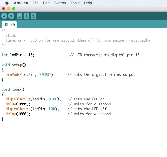
About the code
- we set our pin (13) as output on setup() function
- turns on the LED using digitalWrite(ledPin, HIGH) function
- wait for 1000 mili seconds using delay(1000) function
- turns off the LED using digitalWrite(ledPin, LOW)
- wait for 1000 mili seconds using delay(1000) function
- and the loop goes on forever!
Well as long as the microcontroller is powered up, it will blink forever.
LED Brightness
Changing the brightness is a different thing.
We will still be using our circuit but we have to change the digital pin 13 to a pin with PWM capable.
If you see this sign ~9 or any number means its capable of PWM.
Change the end of jumper wire from digital pin 13 to pin 9.
Download the program file attached and open it.
Click the arrow icon or Upload button. And see what magic happens!
Your LED is blinking in fade in fade out animation!
LED gets lit by changing voltage given to it.
About the code
Add lit status
bool onLed = true;
Add brightness value (0~255)
int val = 0;
If the status of onLed is true increase brightness else decrease
if(onLed)
    val++;       // increase brightness
else
    val--;       //decrease brightness
Update LED brightness
analogWrite(ledPin, val);
If the brightness reached the maximum value, change onLed status to false
else if 0 change onLed status to true and wait for 1000 miliseconds
then wait for 10 miliseconds
if(val==255)
    onLed = false;              // turns off LED
else if(val==0){
    onLed = true;               // lights on LED
    delay(1000);                 // waits for a second before on again
}
     delay(10);
More LED Be a Maker!
; ; 1 / 2Take control of what you can do! Add more LED, add more code and start to have fun!
Good luck! :)
Schematics, diagrams and documents
Code
Credits
Related products


Leave your feedback...