

Items used in this project

Story
LCD Arduino project brief introduction
Some time ago, I found a heart rate sensor module MAX30100 in shopping online. This module can collect blood oxygen and heart rate data of users, which is also simple and convenient to use.
According to the data, I found that there are libraries of MAX30100 in the Arduino library files. That is to say, if I use the communication between LCD Arduino and MAX30100, I can directly call the Arduino library files without having to rewrite the driver files. This is a good thing, so I bought the module of MAX30100.
I decided to use Arduino to verify the heart rate and blood oxygen collection function of MAX30100. With STONE TFT LCD screen for monitoring blood pressure.
.webp)
Note: this module by default only with 3.3 V level MCU communications, because it defaults to using IIC pin pull up the resistance of 4.7 K to 1.8 V, so there is no communication with the Arduino by default, if you want to commune with the Arduino and need two 4.7 K of the IIC pin pull-up resistor connected to the VIN pin, these contents will be introduced in the back of the chapter.
Functional assignments
Before starting this project, I thought about some simple features:
• Heart rate data and blood oxygen data were collected
• Heart rate and blood oxygen data are displayed through an LCD screen
These are the only two features, but if we want to implement it, we need to do more thinking:
• What master MCU is used?
• What kind of LCD display?
As we mentioned earlier, we use Arduino for the MCU, but this is an LCD Arduino project, so we need to choose the appropriate LCD display module. I plan to use the LCD display screen with a serial port. I have a STONE STVI070WT-01 displayer here, but if Arduino needs to communicate with it, MAX3232 is needed to do the level conversion.
Then the basic electronic materials are determined as follows:
1. Arduino Mini Pro development board
2. MAX30100 heart rate and blood oxygen sensor module
3. STONE STVI070WT-01 LCD serial port display module
4. MAX3232 module
Hardware Introduction
MAX30100
The MAX30100 is an integrated pulse oximetry and heart rate monitor sensor solution. It combines two LEDs, a photodetector, optimized optics, and low-noise analog signal processing to detect pulse oximetry and heart-rate signals. The MAX30100 operates from 1.8V and 3.3V power supplies and can be powered down through software with negligible standby current, permitting the power supply to remain connected at all times.
Applications
● Wearable Devices
● Fitness Assistant Devices
● Medical Monitoring Devices
Benefits and Features
1、Complete Pulse Oximeter and Heart-Rate SensorSolution Simplifies Design
• Integrated LEDs, Photo Sensor, and high-Performance Analog Front -End
• Tiny 5.6mm x 2.8mm x 1.2mm 14-Pin OpticallyEnhanced System-in-Package
2、Ultra-Low-Power Operation Increases Battery Life for wearable Devices
• Programmable Sample Rate and LED Current for Power Savings
• Ultra-Low Shutdown Current (0.7µA, type)
3、Advanced Functionality Improves Measurement Performance
• High SNR Provides Robust Motion Artifact Resilience
• Integrated Ambient Light Cancellation
• High Sample Rate Capability
• Fast Data Output Capability
Detection Principle
.webp)
Just press your finger against the sensor to estimate pulse oxygen saturation (SpO2) and pulse (equivalent to heartbeat).
The pulse oximeter (oximeter) is a mini-spectrometer that USES the principles of different red cell absorption spectra to analyze the oxygen saturation of the blood. This real-time and rapid measurement method is also widely used in many clinical references.
I will not introduce the MAX30100 too much, because these materials are available on the Internet. Interested friends can look up the information of this heart rate test module on the Internet, and have a deeper understanding of its detection principle.
Introduction to the STVI070WT-01 displayer
In this project, I will use the STONE STVI070WT-01 to display the heart rate and blood oxygen data.
The driver chip has been integrated inside the display screen, and there is software for users to use. Users only need to add buttons, text boxes, and other logic through the designed UI pictures, and then generate configuration files and download them into the display screen to run.
The display of STVI070WT-01 communicates with MCU through the UART RS232 signal, which means that we need to add a MAX3232 chip to convert the RS232 signal into a TTL signal so that we can communicate with Arduino MCU.
.webp)
If you are not sure how to use the MAX3232, please refer to the following pictures:
.webp)
If you think the level conversion is too troublesome, you can choose other types of displayers of STONE Tech, some of which can directly output UART-TTL signal.
The official website has detailed information and an introduction:
If you need video tutorials and tutorials to use, you can also find it on the official website.
.webp)
Development steps
Three steps of STONE display screen development:
• Design the display logic and button logic with STONE TOOL software and download the design file to the display module.
• MCU communicates with the STONE LCD display module through the serial port.
• With the data obtained in step 2, the MCU does other actions.
STONE TOOL software installation
Download the latest version of the STONE TOOL software (currently TOOL2019) from the website, and install it.
After the software is installed, the following interface will be opened:
.webp)
Click the "File" button in the upper left corner to create a new project, which we will discuss later.
Arduino is an open-source electronic prototype platform that is easy to use and easy to use. It includes the hardware part (various development boards that conform to the Arduino specification) and the software part (Arduino IDE and related development kits).
The hardware part (or development board) consists of a microcontroller (MCU), Flash memory (Flash), and a set of universal input/output interfaces (GPIO), which you can think of as a microcomputer motherboard.
The software part is mainly composed of Arduino IDE on PC, related board-level support package (BSP), and rich third-party function library. With the Arduino IDE, you can easily download the BSP associated with your development board and the libraries you need to write your programs.
Arduino is an open-source platform. So far, there have been many models and many derived controllers, including Arduino Uno, Arduino Nano, Arduino Yun, and so on. In addition, the Arduino IDE now not only supports the Arduino series development boards but also adds support for popular development boards such as Intel Galileo and NodeMCU by introducing BSP.
Arduino senses the environment through a variety of sensors, controlling lights, motors, and other devices to feedback and influence the environment. The microcontroller on the board can be programmed with an Arduino programming language, compiled into binaries, and burned into the microcontroller. Programming for Arduino is implemented with the Arduino programming language (based on Wiring) and the Arduino development environment (based on Processing). Arduino-based projects can contain Arduino only, as well as Arduino and other software running on PC, and they communicate with each other (such as Flash, Processing, MaxMSP).
HMI for Arduino display serial TFT LCD project development environment
The Arduino development environment is the Arduino IDE, which can be downloaded from the Internet.
Log into the official website of Arduino and download the software
https://www.arduino.cc/en/Main/Software?setlang=cn
After installing the Arduino IDE, the following interface will appear when you open the software:
.webp)
The Arduino IDE creates two functions by default: the setup function and the loop function.
There are many Arduino introductions on the Internet. If you don't understand something, you can go to the Internet to find it.
LCD Arduino Project implementation process
hardware connection
To ensure that the next step in writing code goes smoothly, we must first determine the reliability of the hardware connection.
Only four pieces of hardware were used in this project:
1. Arduino Mini pro-development board
2. STONE STVI070WT-01 TFT-LCD display screen
3. MAX30100 heart rate and blood oxygen sensor
4. MAX3232 (rs232-> TTL)
The Arduino Mini Pro development board and STVI070WT-01 TFT-LCD display screen are connected through UART, which requires level conversion through MAX3232, and then the Arduino Mini Pro development board and MAX30100 module are connected through the IIC interface. After thinking clearly, we can draw the following wiring picture:
.webp)
.webp)
Make sure there are no errors in the hardware connection and proceed to the next step.
STONE TFT LCD user interface design
First of all, we need to design a UI display image, which can be designed by PhotoShop or other image design tools. After designing the UI display image, save the image in JPG format.
Open the software STONE TOOL 2019 and create a new project:
.webp)
.webp)
Remove the image that was loaded by default in the new project, and add the UI image that we designed.
Add the text display component, design the display digit and decimal point, get the storage location of the text display component in the displayer.
The effect is as follows:
.webp)
Text display component address:
• Connection sta : 0x0008
• Heart rate : 0x0001
• Blood oxygen : 0x0005
The main contents of the UI interface are as follows:
• Connection status
• Heart rate display
• Blood oxygen showed
Generate configuration file
Once the UI design is complete, the configuration file can be generated and downloaded to the STVI070WT-01 display.
.webp)
First, perform step 1, then insert the USB flash drive into the computer, and the disk symbol will be displayed. Then click "Download to u-disk" to Download the configuration file to the USB flash drive, and then insert the USB flash drive into STVI070WT-01 to complete the upgrade.
MAX30100
MAX30100 communicates via IIC. Its working principle is that the ADC value of heart rate can be obtained through infrared led irradiation. The MAX30100 register can be divided into five categories: state register, FIFO, control register, temperature register, and ID register. The temperature register reads the temperature value of the chip to correct the deviation caused by the temperature. The ID register can read the chip's ID number.
.webp)
MAX30100 is connected with the Arduino Mini Pro development board through the IIC communication interface. Because there are ready-made MAX30100 library files in the Arduino IDE, we can read the heart rate and blood oxygen data without studying the registers of MAX30100.
For those who are interested in exploring the MAX30100 register, see the MAX30100 Datasheet.
Modify the MAX30100 IIC pull-up resistor
It should be noted that the 4.7k pull-up resistance of the IIC pin of the MAX30100 module is connected to 1.8v, which is not a problem in theory. However, the communication logic level of the Arduino IIC pin is 5V, so it cannot communicate with Arduino without changing the hardware of the MAX30100 module. Direct communication is possible if the MCU is STM32 or another 3.3v logic level MCU.
Therefore, the following changes need to be made:
.webp)
Remove the three 4.7k resistors marked in the picture with an electric soldering iron. Then weld two resistors of 4.7k at the pins of SDA and SCL to VIN, so that we can communicate with Arduino.
Arduino serial display LCD
Open the Arduino IDE and find the following buttons:
.webp)
Search for "MAX30100" to find two libraries for MAX30100, then click download and install.
.webp)
After the installation, you can find the Demo of MAX30100 in the LIB library folder of LCD Arduino:
.webp)
Double-click the file to open it.
.webp)
This Demo can be directly tested. If the hardware connection is ok, you can download the code compilation into the Arduino development board and see the data of MAX30100 in the serial debugging tool.
The complete code is as follows:
/*
Arduino-MAX30100 oximetry / heart rate integrated sensor library
Copyright (C) 2016 OXullo Intersecans
This program is free software: you can redistribute it and/or modify
it under the terms of the GNU General Public License as published by
the Free Software Foundation, either version 3 of the License, or
(at your option) any later version.
This program is distributed in the hope that it will be useful,
but WITHOUT ANY WARRANTY; without even the implied warranty of
MERCHANTABILITY or FITNESS FOR A PARTICULAR PURPOSE. See the
GNU General Public License for more details.
You should have received a copy of the GNU General Public License
along with this program. If not, see.
*/
#include
#include "MAX30100_PulseOximeter.h"
#define REPORTING_PERIOD_MS 1000
// PulseOximeter is the higher level interface to the sensor
// it offers:
// * beat detection reporting
// * heart rate calculation
// * SpO2 (oxidation level) calculation
PulseOximeter pox;
uint32_t tsLastReport = 0;
// Callback (registered below) fired when a pulse is detected
void onBeatDetected()
{
Serial.println("Beat!");
}
void setup()
{
Serial.begin(115200);
Serial.print("Initializing pulse oximeter..");
// Initialize the PulseOximeter instance
// Failures are generally due to an improper I2C wiring, missing power supply
// or wrong target chip
if (!pox.begin()) {
Serial.println("FAILED");
for(;;);
} else {
Serial.println("SUCCESS");
}
// The default current for the IR LED is 50mA and it could be changed
// by uncommenting the following line. Check MAX30100_Registers.h for all the
// available options.
// pox.setIRLedCurrent(MAX30100_LED_CURR_7_6MA);
// Register a callback for the beat detection
pox.setOnBeatDetectedCallback(onBeatDetected);
}
void loop()
{
// Make sure to call update as fast as possible
pox.update();
// Asynchronously dump heart rate and oxidation levels to the serial
// For both, a value of 0 means "invalid"
if (millis() - tsLastReport > REPORTING_PERIOD_MS) {
Serial.print("Heart rate:");
Serial.print(pox.getHeartRate());
Serial.print("bpm / SpO2:");
Serial.print(pox.getSpO2());
Serial.println("%");
tsLastReport = millis();
}
}
.webp)
This code is very simple, I believe you can understand it at a glance. I have to say that the modular programming of Arduino is very convenient, and I don't even need to understand how the driver code of Uart and IIC is implemented.
Of course, the above code is an official Demo, and I still need to make some changes to display the data to STONE's displayer.
Display data to the STONE display through Arduino LCD
First, we need to get the address of the component that displays the heart rate and blood oxygen data in STONE's displayer:
In my project, the address is as follows:
Heart rate display component address: 0x0001
Address of blood oxygen display module: 0x0005
Sensor connection status address: 0x0008
If you need to change the display content in the corresponding space, you can change the display content by sending data to the corresponding address of the display screen through the serial port of Arduino.
The modified code is as follows:
/*
Arduino-MAX30100 oximetry / heart rate integrated sensor library
Copyright (C) 2016 OXullo Intersecans
This program is free software: you can redistribute it and/or modify
it under the terms of the GNU General Public License as published by
the Free Software Foundation, either version 3 of the License, or
(at your option) any later version.
This program is distributed in the hope that it will be useful,
but WITHOUT ANY WARRANTY; without even the implied warranty of
MERCHANTABILITY or FITNESS FOR A PARTICULAR PURPOSE. See the
GNU General Public License for more details.
You should have received a copy of the GNU General Public License
along with this program. If not, see.
*/
#include
#include "MAX30100_PulseOximeter.h"
#define REPORTING_PERIOD_MS 1000
#define Heart_dis_addr 0x01
#define Sop2_dis_addr 0x05
#define connect_sta_addr 0x08
unsigned char heart_rate_send[8]= {0xA5, 0x5A, 0x05, 0x82,
0x00, Heart_dis_addr, 0x00, 0x00};
unsigned char Sop2_send[8]= {0xA5, 0x5A, 0x05, 0x82, 0x00,
Sop2_dis_addr, 0x00, 0x00};
unsigned char connect_sta_send[8]={0xA5, 0x5A, 0x05, 0x82, 0x00,
connect_sta_addr,0x00, 0x00};
// PulseOximeter is the higher level interface to the sensor
// it offers:
// * beat detection reporting
// * heart rate calculation
// * SpO2 (oxidation level) calculation
PulseOximeter pox;
uint32_t tsLastReport = 0;
// Callback (registered below) fired when a pulse is detected
void onBeatDetected()
{
// Serial.println("Beat!");
}
void setup()
{
Serial.begin(115200);
// Serial.print("Initializing pulse oximeter..");
// Initialize the PulseOximeter instance
// Failures are generally due to an improper I2C wiring, missing power supply
// or wrong target chip
if (!pox.begin()) {
// Serial.println("FAILED");
// connect_sta_send[7]=0x00;
// Serial.write(connect_sta_send,8);
for(;;);
} else {
connect_sta_send[7]=0x01;
Serial.write(connect_sta_send,8);
// Serial.println("SUCCESS");
}
// The default current for the IR LED is 50mA and it could be changed
// by uncommenting the following line. Check MAX30100_Registers.h for all the
// available options.
pox.setIRLedCurrent(MAX30100_LED_CURR_7_6MA);
// Register a callback for the beat detection
pox.setOnBeatDetectedCallback(onBeatDetected);
}
void loop()
{
// Make sure to call update as fast as possible
pox.update();
// Asynchronously dump heart rate and oxidation levels to the serial
// For both, a value of 0 means "invalid"
if (millis() - tsLastReport > REPORTING_PERIOD_MS) {
// Serial.print("Heart rate:");
// Serial.print(pox.getHeartRate());
// Serial.print("bpm / SpO2:");
// Serial.print(pox.getSpO2());
// Serial.println("%");
heart_rate_send[7]=(uint32_t)pox.getHeartRate();
Serial.write(heart_rate_send,8);
Sop2_send[7]=pox.getSpO2();
Serial.write(Sop2_send,8);
tsLastReport = millis();
}
}
Compile the code, download it to the Arduino serial display LCD development board, and you're ready to start testing.
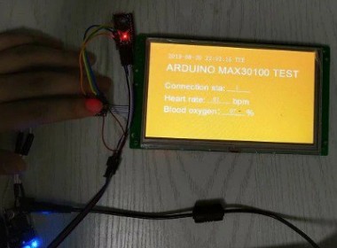
We can see that when the fingers leave the MAX30100, the heart rate and blood oxygen display 0. Place your finger on the MAX30100 collector to see your heart rate and blood oxygen levels in real-time.
STONE LCD Arduino project effect can be seen in the following picture
.webp)
.webp)
Credits
Related products


Leave your feedback...