

Items used in this project
Hardware components

View all
Hand tools and fabrication machines
Story
- Without music, life would be a mistake.
- -- FRIEDRICH NIETZSCHE
Intro
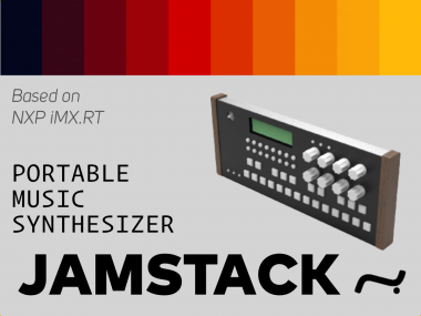
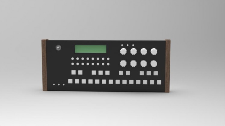
JAMSTACK is an expressive digital music synthesizer, groove box, sampler and effects processor. The workflow is straightforward, with everything accessible within a single push of a button. The interface is clean and simple to use, but most importantly, it encourages experimentation. In these unusual times, our mental well-being and sanity are at stake. Creativity, musical expression, and sensory exploration are arguably the best ways to relax, recharge and transfer yourself to some cosy place where emotional balance can be restored.
NXP's IMXRT series was probably the best choice for such a computationally demanding task – synthesizing sounds, playing high-quality sound samples and performing real-time sound effects, such as filters, waveshapers, etc. I had an idea to create a digital music synthesizer for several years. And there's no better time than now to build a synthesizer, when I know it'll be powered with a 500 MHz Cortex-M7 microprocessor.
Designing custom PCBs
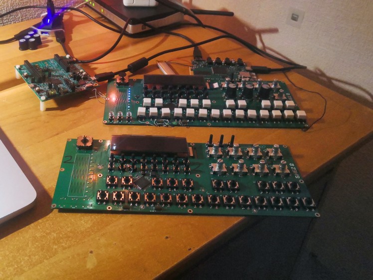
For this hackathon Electromaker provided me with a NXP MIMXRT1010 EVK – 32-bit ARM Cortex-M7 prototyping kit. However, it's really hard to make a hardware music synthesizer on a general-purpose EVK – I can't have ordinary input sources such as piano keyboard, drum pads or step-sequencer buttons. Without them, music-making feels cumbersome and tedious. So I decided to design a custom board incorporating a piano keyboard (using low-cost OMRON buttons), touch slider for expressive note control, 16 functional buttons, OLED display, etc. The hackathon rules specified that "the NXP RT1010 or RT1020 must be used as the development platform for your project", so I decided to make two separate PCB's - one for sound processing using MIMXRT1020 and another for user interface processing and display management using MIMXRT1010.
Synthesizing
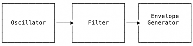
Before diving into the hardware design it's useful to have a basic understanding of what the synthesizer does. There are many methods to create sounds using audio synthesis. At the moment I'll focus only on subtractive synthesis.
Subtractive synthesis is based on the assumption that an acoustic instrument may be represented by a basic oscillator capable of producing waveforms with varied frequency spectrums. The oscillator sends the signal to a filter, which reflects the frequency-dependent losses and resonances in the instrument's body. The synthesizer's envelope generator shapes the filtered signal over time.
Common oscillator waveforms

Simple additive synthesis diagram
Sound example of audio synthesis used in JAMSTACK. (Warning: watch out your audio volume!)
Specification
Sound and power board:
- Cortex-M7 CPU @ 500 MHz
- 256 KB SRAM
- 32 MB RAM
- 8 MB Flash
- SD Card slot
- Line level input
- Microphone input
- Line out
- Headphone out
- External MIDI input
- Battery powered operation
- Integrated OpenSDA circuit for easier development
User interface board:
- Musical (piano) keyboard
- 16 + 6 functional buttons
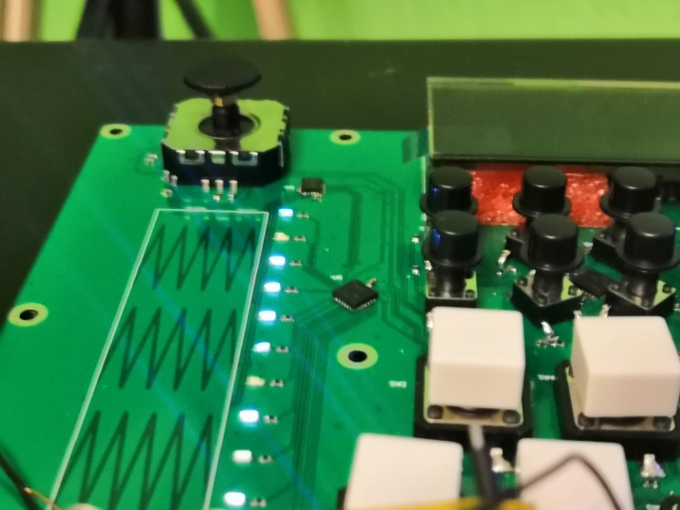
- Touch strip with LED bar
- Joystick
- 6 DOF Inertial measurement unit
- 8 rotary encoders with push-buttons
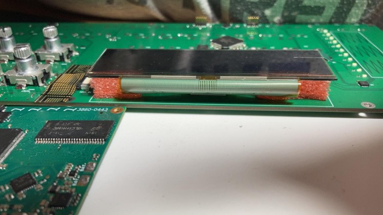
- OLED display
- External SWD flashing and debugging
Prototype design
To complete both boards I used design files provided by NXP for MIMXRT1010-EVK and MIMXRT1020-EVK. The EVKs for both MCUs helped a lot at figuring out how to design the power management for the microcontrollers and greatly speed up SDRAM layout as the SDRAM placement and PCB space requirements have been already established. Nevertheless the decoupling capacitors still posed a challenge to be kept as close as possible to the chips and for most of the GPIOs to be still usable at the same time.
Dual board construction was a design choice brought up from the need to have a 4 layer stack-up for USB impedance matching and a large but not as complex PCB for keyboard and display. The two boards are connected through a flat flex cable which routes main power and I2C, UART, power management and other GPIO signals. UART is primarily used for communication between two microprocessors.
Due to mixed signal design I opted to using 4-layer PCB. Another design consideration was to use as many SMD components as possible to reduce manual labour required for assembly. I chose to use the cheapest PCB manufacturing option of 6mil traces and gaps as this was sufficient for QFP package of the RT1120 microcontroller.
The audio block of the system is powered by TLV320AIC3104 codec which is a budget stereo ADC and stereo DAC IC with a small DSP. I chose to use this codec because of its cheap price and better than average SNR spec.
I added a differential MEMS microphone as well as options to connect LINE IN and LINE OUT. Headphone output was also a necessary addition. An array of electrolytic capacitors were required to be put in the audio signal paths to protect external devices from common-mode DC voltage that is required for the codec to operate.
One of the main challenges was to incorporate analog part of the codec into the noisy environment present on the PCB. So to isolate the analog part I split the ground planes into digital and analog which later showed to not solve any noise issues.
The memory part of the circuit contains 256Mb 167MHz DRAM, 64Mb 133MHz Quad-SPI flash and an optional 128Kb EEPROM. When it came to choosing DRAM and flash memory I did so as to not stray too much from EVK design from NXP to reduce the risk of having unsupported boot memory and/or having unsupported RAM.
Since the device would be battery powered I have added a battery charger IC to the design which would not only charge the battery but also provide 3.7V nominal system power through its power-path. The system power is then connected to multiple LDO regulators which are 3.3V SNVS regulator that is always on, 3.3V buck system regulator that is enabled by IMXRT1020 when system is turned on, further I have SDIO buck regulator that can switch between 1.8V and 3.3V depending on the memory card requirements and lastly a 3.3V LDO regulator for analog circuitry.
Main USB connector is routed to the MCU and is set up as a downstream port and works as a class compliant MIDI device. In addition to that this port is a power entry to charge and power the device with up to 3A sink capability which is activated through two 5.1k resistors on CC lines.
Rotary encoders brought up its own set of challenges, main of which is to have a way to service 16 GPIOs in a very quick manner as to not skip any encoder steps. So it necessitated use of a separate microcontroller for facilitating just the encoder reading function.
The peripherals on board which consist of GPIO expanders, touch sensor, IMU and rotary encoder rely extensively on I2C to communicate with the MCU. All of the mentioned peripherals share the same I2C bus as well as same interrupt signal and have been assigned different slave addresses in hardware.
For debugging purposes I reused EVK's OpenSDA circuit with with minor simplifications (eliminating some JTAG signals) and put 0R resistors between the debugger and the target MCU for the ability to reuse the debugger for other projects. For the sake of using same cables for everything I used a USB-C connector instead of micro-USB in the design.
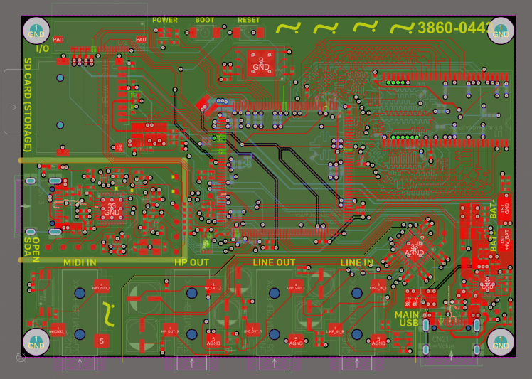
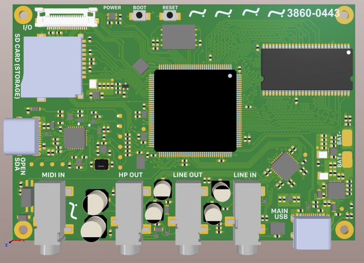
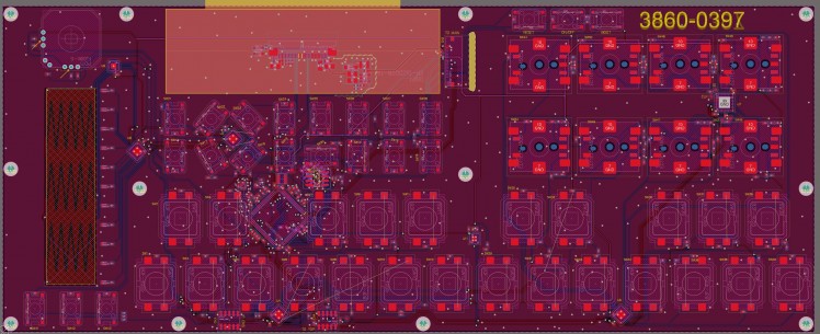
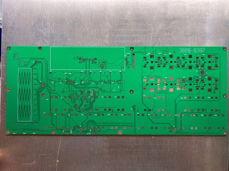
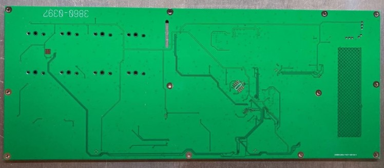
Final PCB design of main board (audio + power)
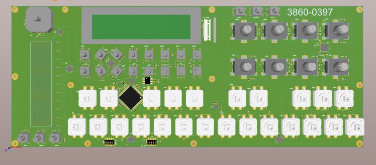
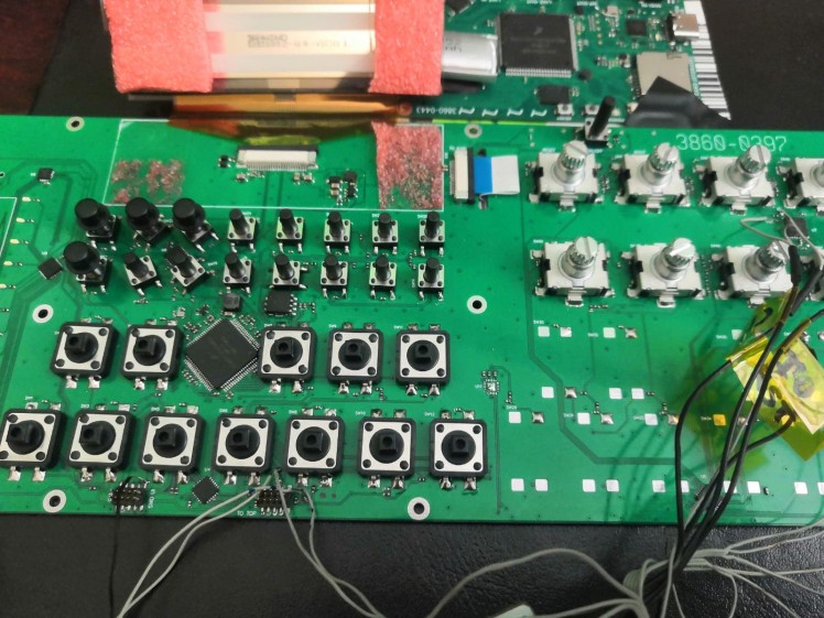
Final PCB design of user interface board
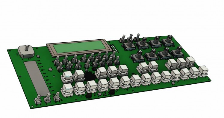
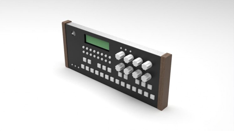
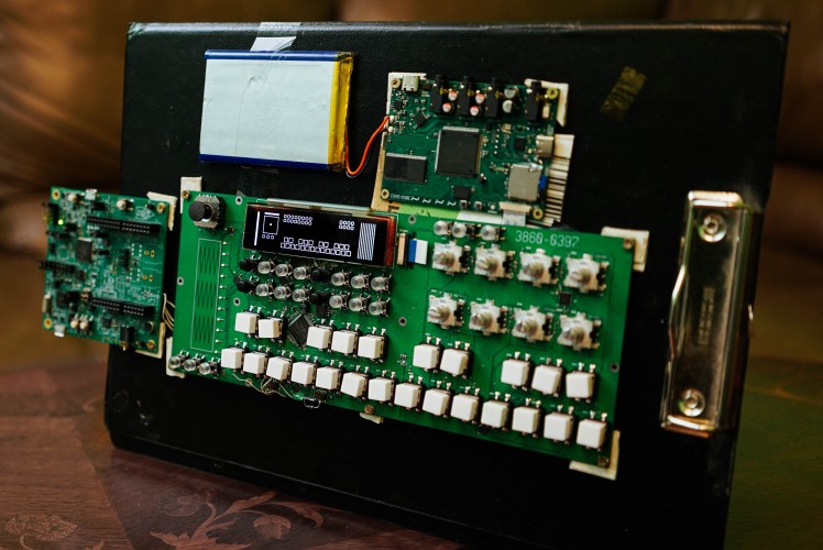
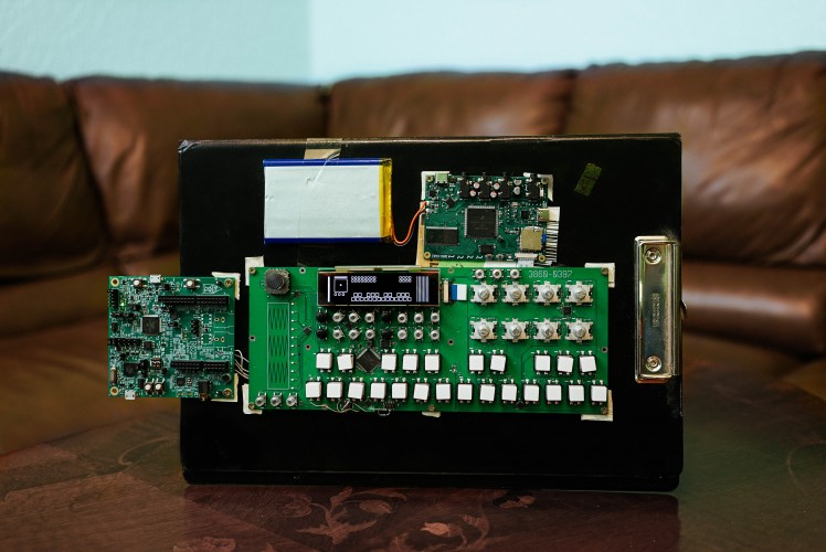
Prototype with enclosure
Production of the prototype
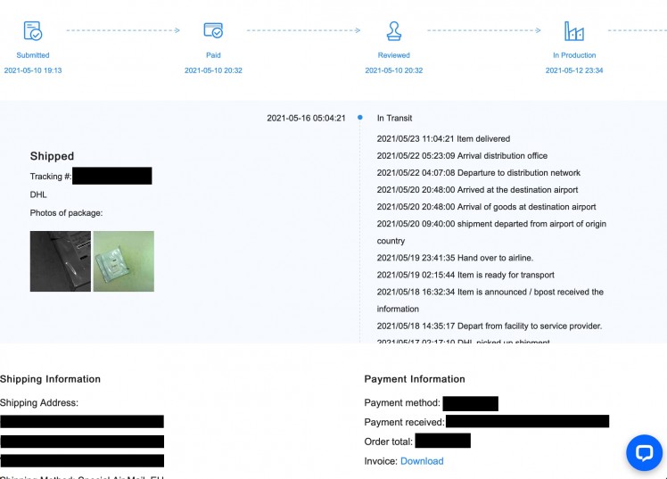
Boards ordered from fabrication house

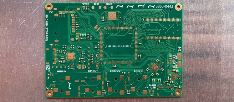
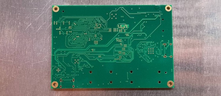
Prototype PCBs received
Fast shipping is my savior
PCB: Main board (audio + power)
PCB: User interface board
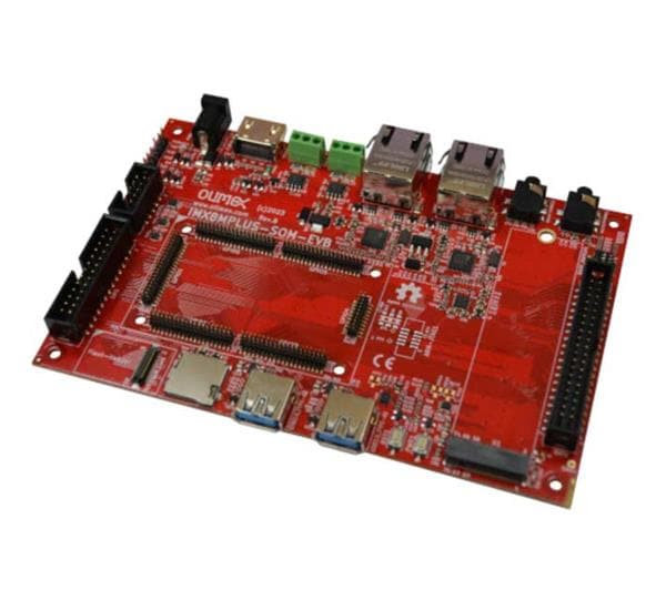
EVK from Electromaker
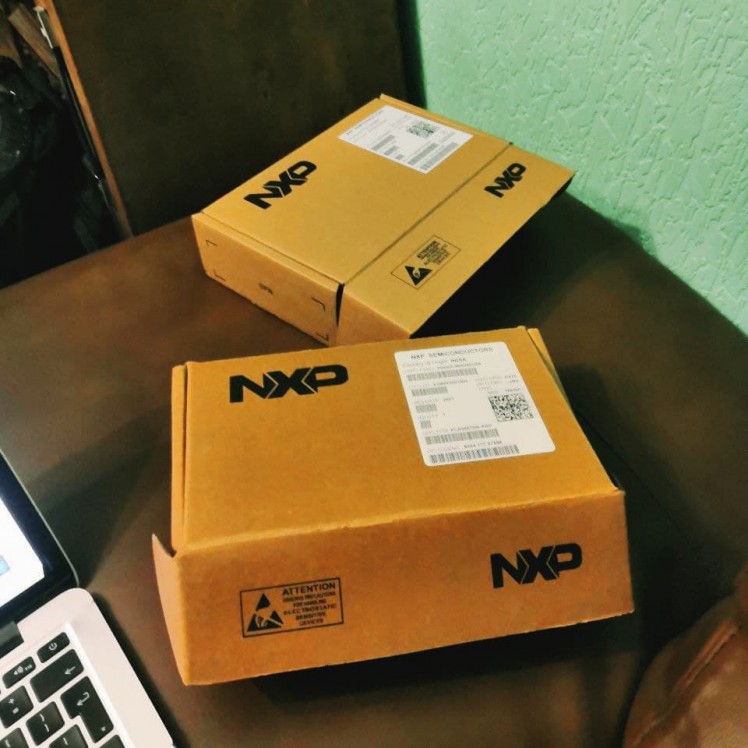
Sourcing the parts
With current shortage of hardware parts in mind I consider myself lucky enough. I was able to find almost all main parts for my project - MIMXRT1010, MIMXRT1020, audio codec, ram, flash chip, etc. However, I couldn't find an IMU ICM20948 and some other parts. My suppliers was Mouser, DigiKey and LCSC.
Assembly
Assembly process was moderately simple as almost all of the components have been placed on one side of the UI board as well as all but one are SMD type.
The main board on the other hand required a more complex assembly and I outsourced part of the assembly (only passives to save on cost) to offshore PCB house and both sides of the PCB required careful and dense component placement.
Big part of the passives were 100nF capacitors which sized to be 0402 as a smaller variety would greatly hinder my assembly efforts.

Firmware
For the firmware, I chose to use both C and C++.
Creating firmware can be a difficult task. Usually, microcontroller manufacturers provide their own frameworks and code samples. Vendor examples are great: they provide a good starting point. They are not optimized, and this is intentional. But they might come with features and functions we don't need. Knowing different ways to optimize the application with cutting off features or tuning settings can be very useful to optimize RAM and flash usage. While analyzing NXP's FSL I noticed many strange things.
First, I tried to combine several examples from NXP examples folder to just test the EVK and immediately hit a roadblock – my code was too big and it didn't fit into RAM. The problem was FSL – I had to rewrite parts of the implementation to just be able to run the code.
Since then I understood that I'll have to write a lot of custom code and deviate from "standard" NXP's hardware abstraction layer – FSL.
Startup
The startup procedure is fairly standard according to FSL convention.
- BOARD_InitBootPins();
- BOARD_InitSDRAMPins();
- BOARD_InitBootClocks();
- BOARD_InitBootPeripherals();
- BOARD_InitDebugConsole();
However, later I'm calling custom init procedures.
- systick_init();
- usb_pll_start();
- usb_init();
- i2c_begin();
- uart_init();
- codec_init();
Power on / off
Since I'm using a button which is directly connected to ONOFF pin on IMXRT MCU, I need to utilize special ISR to catch when user clicks it.
ISR code
- extern "C" void SNVS_LP_WRAPPER_IRQHandler(void)
- {
- if(SNVS_HPSR & 0x40)
- {
- SNVS_HPCOMR |= (1 << 31); //| (1 << 4);
- SNVS_LPSR |= (1 << 18) | (1 << 17);
- PRINTF("SNVS ISR rn");
- gShutdownRequested = true;
- }
- else
- {
- PRINTF("ERR! SNVS ISR ELSE rn");
- while(1) {}
- }
- }
Set up the ISR
- if(gFeatureShutdownManagement)
- {
- SNVS_LPSR |= (1 << 18) | (1 << 17);
- __NVIC_ClearPendingIRQ(SNVS_LP_HP_WRAPPER_IRQn);
- __NVIC_SetPriority(SNVS_LP_HP_WRAPPER_IRQn, 255); // lowest
- // memory barrier
- asm volatile("dsb");
- EnableIRQ(SNVS_LP_HP_WRAPPER_IRQn);
- }
Later in the main function I'm checking if ISR requested power down.
- if(gShutdownRequested)
- {
- SNVS_LPSR |= (1 << 18) | (1 << 17);
- __disable_irq();
- __NVIC_ClearPendingIRQ(SNVS_LP_HP_WRAPPER_IRQn);
- PRINTF("Power off nowrn");
- gShutdownRequested = false;
- // Power off
- SNVS->LPCR |= SNVS_LPCR_TOP_MASK;
- asm volatile("dsb");
- while(1)
- {
- asm("wfi");
- }
- }
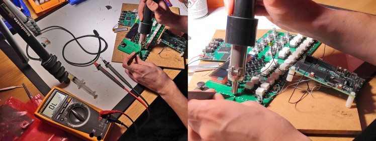
Testing all GPIOs
Using EVK for debugging
Debugging UI board using MIMXRT1010-EVK
Audio library design
Most audio synthesizers or even audio players uses double-buffering, also know as ping-pong buffer technique. It's well known audio scheduling technique described in many books.
As noted in application note from NXP, at any one time, one buffer is actively being played (the front buffer), while the second (background) buffer is filled with the new audio samples. When playing is completed, the roles of the two buffers are switched. This is usually accomplished by switching the pointers.
Direct memory access is ensured by the DMA controller, which is a special MCU peripheral capable of transferring large blocks of data between memory locations with no CPU assistance needed.
The software initializes a DMA channel with the DMA transfer attributes, the source and destination memory address, the number of bytes transferred in the minor loop (single memory access) and the number of minor loops inside the major loop, which defines the total size of the transferred data block. The source/destination address is incremented automatically after the completion of every minor loop. When the complete block has been transferred (the major loop done), the IRQ is generated by the DMA channel. Two separated or adjacent physical SRAM memory arrays are used to create two ping- pong buffers.
To utilize "threads" without using RTOS I chose to setup a "software ISR" which would trigger calculations of all DSP related functions. This design is similar to how music production software works on general purpose computers. The most important thing is to calculate everything within a pre-defined time window, which is roughly every 3ms.
Audio library test in simulation environment. (Warning: watch out your audio volume!)
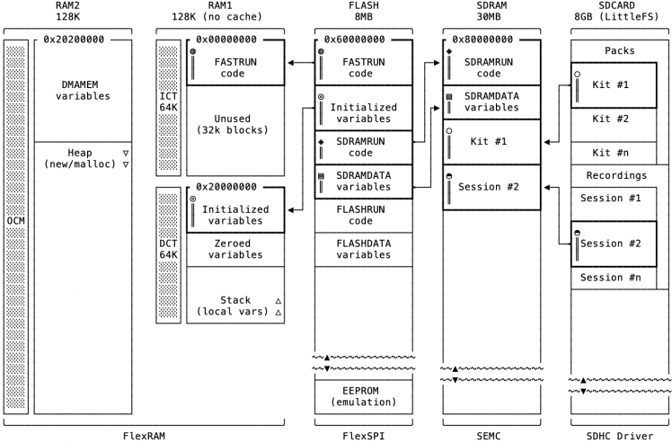
Memory map
Inefficient memory access is a major reason for poor performance. A lot of the source code out there, especially legacy code, was not written with multi-megahertz embedded processors sporting several cache levels in mind. Memory access latency on these devices has a much larger impact to performance than the difference of a single unnecessary extra instruction in an inner loop. As far as mobile devices are concerned, battery life depends on efficient cache utilization more than on anything else.
IMXRT1020 features:
- ITCM 64KB - Instruction Tightly Coupled Memory
- DTCM 64KB - Data Tightly Coupled Memory
- OCRAM 128KB – On Chip RAM
By default, FSL caches both ITC and DTC. However, ITC is very fast. Do we really need to cache it? In this project I left it unchached.
Memory layout for the main MCU
Custom linker scripts
I wanted to place certain code blocks to different memories so first I had to either switch to GNU linker scripts (LD) or utilize managed linker scripts embedded in MCUXPRESSO IDE. On the one hand, managed linker scripts are fantastic because they simplify the otherwise complicated GNU linker script management. On the other hand, it is necessary to understand how to modify them in the event when "non-standard" behavior is required.
For example, I wanted to change the location of the heap, so I created a file in my project subdirectory "jamstack/code/linkscripts/stack_heap_sdk_postdata.ldt":
- <#if HEAP_STACK_STYLE?? && HEAP_STACK_STYLE == "sdk">
- <#if HEAP_LOCATION == "Post Data">
- /* Reserve and place Heap within memory map */
- _HeapSize = ${HEAP_SIZE};
- _zm_heap_start = ADDR(.data_RAM3) + SIZEOF(.data_RAM3) + SIZEOF(.bss_RAM3) + SIZEOF(.noinit_RAM3);
- _zm_heap_end = ORIGIN(SRAM_OC) + LENGTH(SRAM_OC);
- _zm_heap_len = _zm_heap_end - _zm_heap_start;
- .heap : ALIGN(${bss_align})
- {
- ${heap_symbol} = .;
- . += _zm_heap_len;
- . = ALIGN(${bss_align});
- _pvHeapLimit = .;
- } > ${HEAP_REGION}
- </#if>
- <#if STACK_LOCATION == "Post Data">
- /* Reserve and place Stack within memory map */
- _StackSize = ${STACK_SIZE};
- .stack : ALIGN(${bss_align})
- {
- _vStackBase = .;
- . += _StackSize;
- . = ALIGN(${bss_align});
- _vStackTop = .;
- } > ${STACK_REGION}
- </#if>
- </#if>
Buffers for DMA in OCRAM
While coding audio library I had to find out where to put audio buffers (arrays) for DMA. I thought the fastest possible memory – DCTM – would be the best choice. However:
- TCM shows high performance accessed by MCU core.
- OCRAM shows higher performance than TCM when accessed by DMA, while lower performance when accessed by MCU core. The reason is that OCRAM and DMA are in this same bus fabric, with less latency during the access.
- All TCM interfaces run at the same frequency as the Arm Cortex-M7 core and are synchronous to each other.
- The OCRAM controller is connected through the 64-bit AXI bus to one slave port of the interconnect bus fabric (NIC). This slave port frequency is limited to 1⁄4 of the core frequency. For example, if the Arm Cortex-M7 core runs at 528 MHz, then the AXI bus connected to the OCRAM controller is limited to 132 MHz. Expect performance degradation in the data access to the OCRAM in comparison to the xTCM memories. The L1 CACHE memory can help with that.
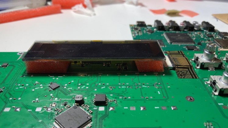
OLED display
The implementation of OLED was quite straightforward. I used 4 wire SPI over FSL's SPI driver.
Demo
Here's a short video showcasing working prototype of JAMSTACK synthesizer. (Warning: watch out your audio volume!)
Planned features
I spent nearly three months building this project. It was impossible to make anythnig else than a rough synthesizer MVP with basic features – simple sound generating engine, envelope generator, audio amplifier and simple effects rack. However, I plan to continue the development of this project.
TBD:
- Multi-engine synthesizer with swapable slots
- Multi-engine drum box
- Note effets (arpeggiator, sequencer, etc.)
- Sampler with basic sample editor
- Multi-slot effects processor
Farewell
Thank you very much for reading! I had a lot of fun making this project. If you're interested more about hardware and the code of this project I suggest you to check out Github repo attached below.
Credits
Related products


Leave your feedback...