
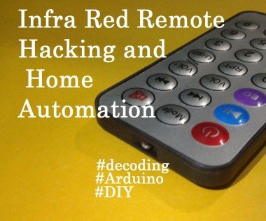
IR Remote Hacking and Automation

Made by SHAMSUDHEEN MARAKKAR
About the project
Hello guys,From my childhood itself I was wondering about the TV remote controller and how does it work.This instructable tells the story how I managed to decode/hack an old remote controller and used it for home automation.This instructable contains different parts as follows: Decoding the remote. Application 1. Application 2. Application 3.
Story
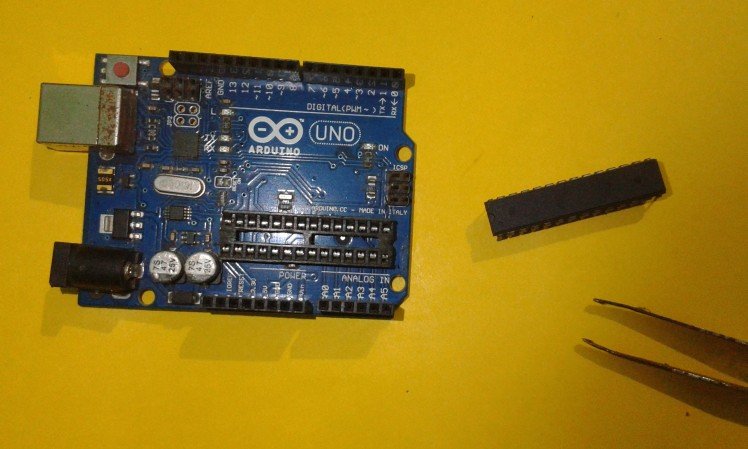
Step 1: Go and Get These Things.
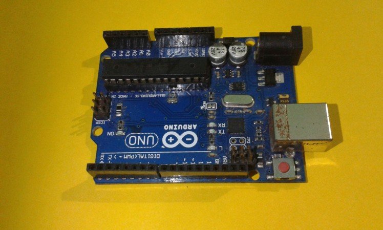


- Arduino Uno.
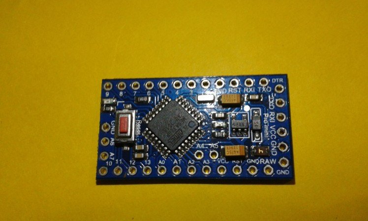
- Arduino pro mini.
- Jumper wires.
- Breadboard.
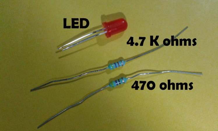
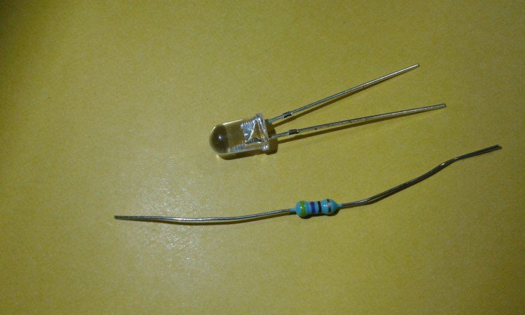
- LED.
- Resistors- 470 Ohms, 4.7 KOhms
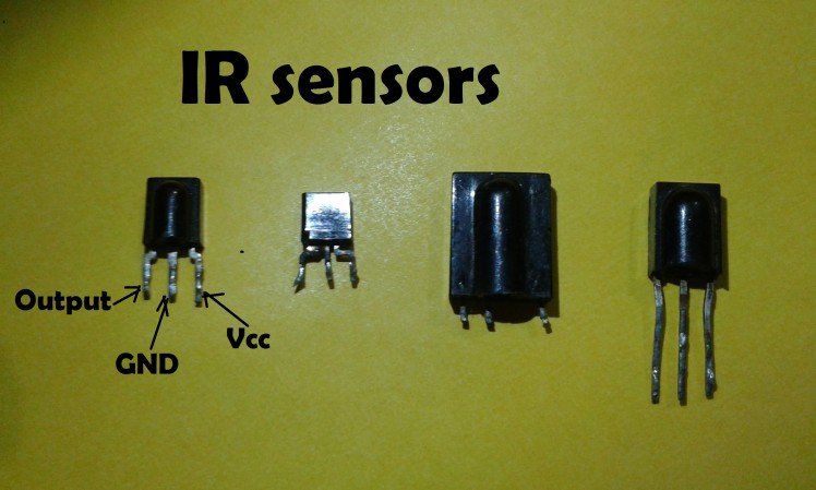
- Infra Red Sensor.
- 5 V DC Relay.
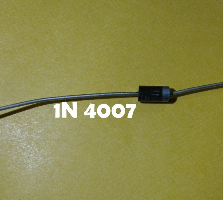
- 1N 4001/ 1N 4007 Diode.
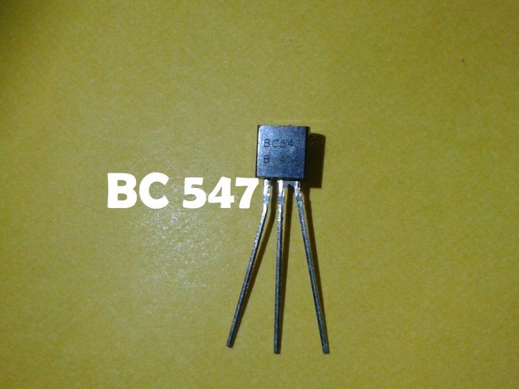
- BC 547 Transistor.
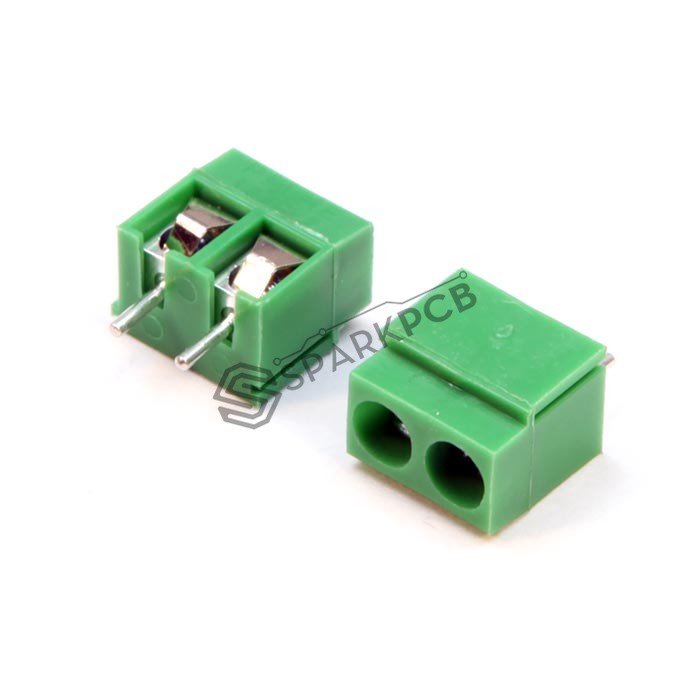
- Terminal connector.
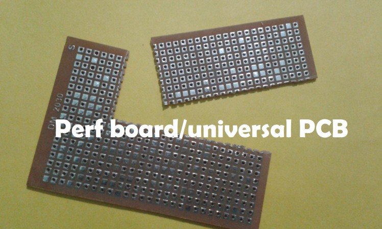
- Universal PCB/Perf board.
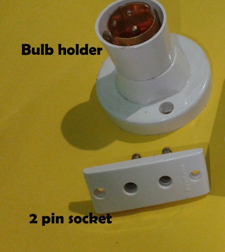
- Bulb holder (AC Bulb holder).
- Wires (For 230 VAC).
- Plug (For 230 VAC).
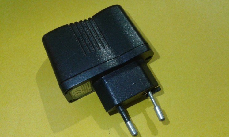
- Old mobile phone charger (Rated 5 V DC).
- Plastic box (As an enclosure).
- Double sided tape.
- Plug socket (For 230 VAC).
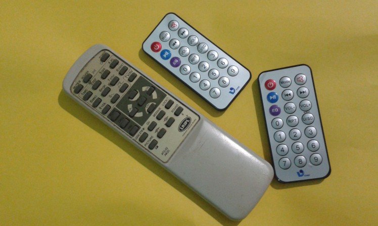
- An old Remote controller.
Step 2: Part 1: Decoding the Remote Controller
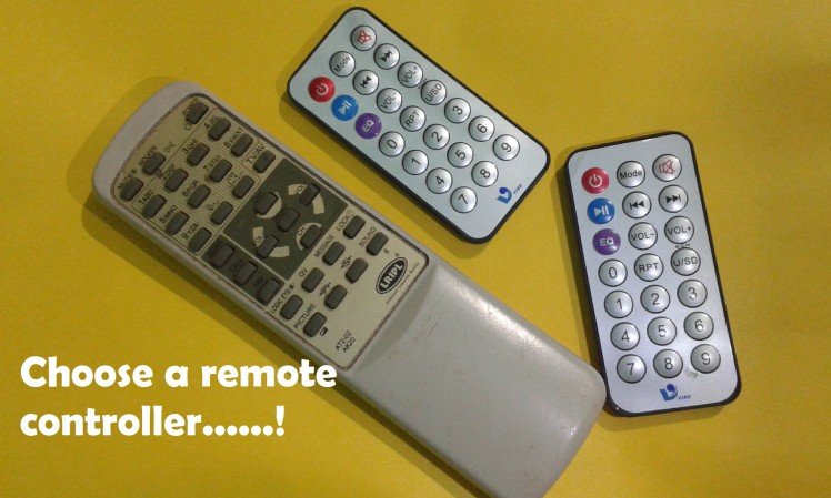
AFTER CHOOSING A WORKING REMOTE CONTROLLER FROM THE OLD REMOTE CONTROLLERS, WE SHOULD KNOW THE
BASICS:
The IR Remote controller consists of an Infra Red LED connected to its circuitry.
When we press any of the buttons, a corresponding code is sent to air via the LED. The code is actually an encoded number, encoded in HEX format. HEX means the base of counting is 16.
ie; In HEX, there are 16 numbers, from 0 to F, as 1,2,3,4,5,6,7,8,9,A,B,C,D,E,F.
So in HEX 25 is (5x16^0)+(2x16^1)=5+32=37
and 5F is (15x16^0)+(5x16)=15+80=95
The HEX code is sent to the IR LED as 1s and 0s (high voltage (3.3V) and low voltage (0 V) respectively).
Suppose, the number 95 is assumed for the VOL+ button. When we press the button, the circuitry sends 95 to the LED as a series of 1s and zeros.
95 is 5F in HEX and this can be written in binary as 0101 1111
ie; 0101 1111=(1x2^0)+(1x2^1)+(1x2^2)+(1x2^3) + (1x2^4)+(0x2^5)+(1x2^6)+(0x2^7)
=1+2+4+8 + 16+0+64+0
=15 + 80
=95
This is the basics of any IR remote controller. Every button is associated with a unique code. What we have to do is decode the number associated with each button of the controller and record it for further reference.
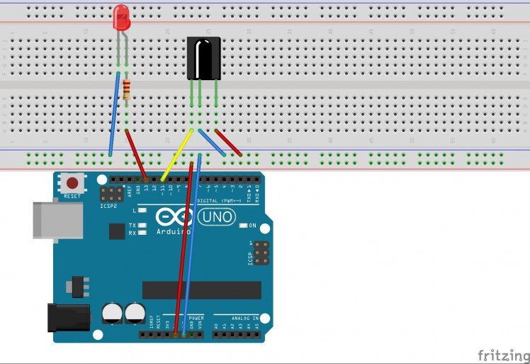
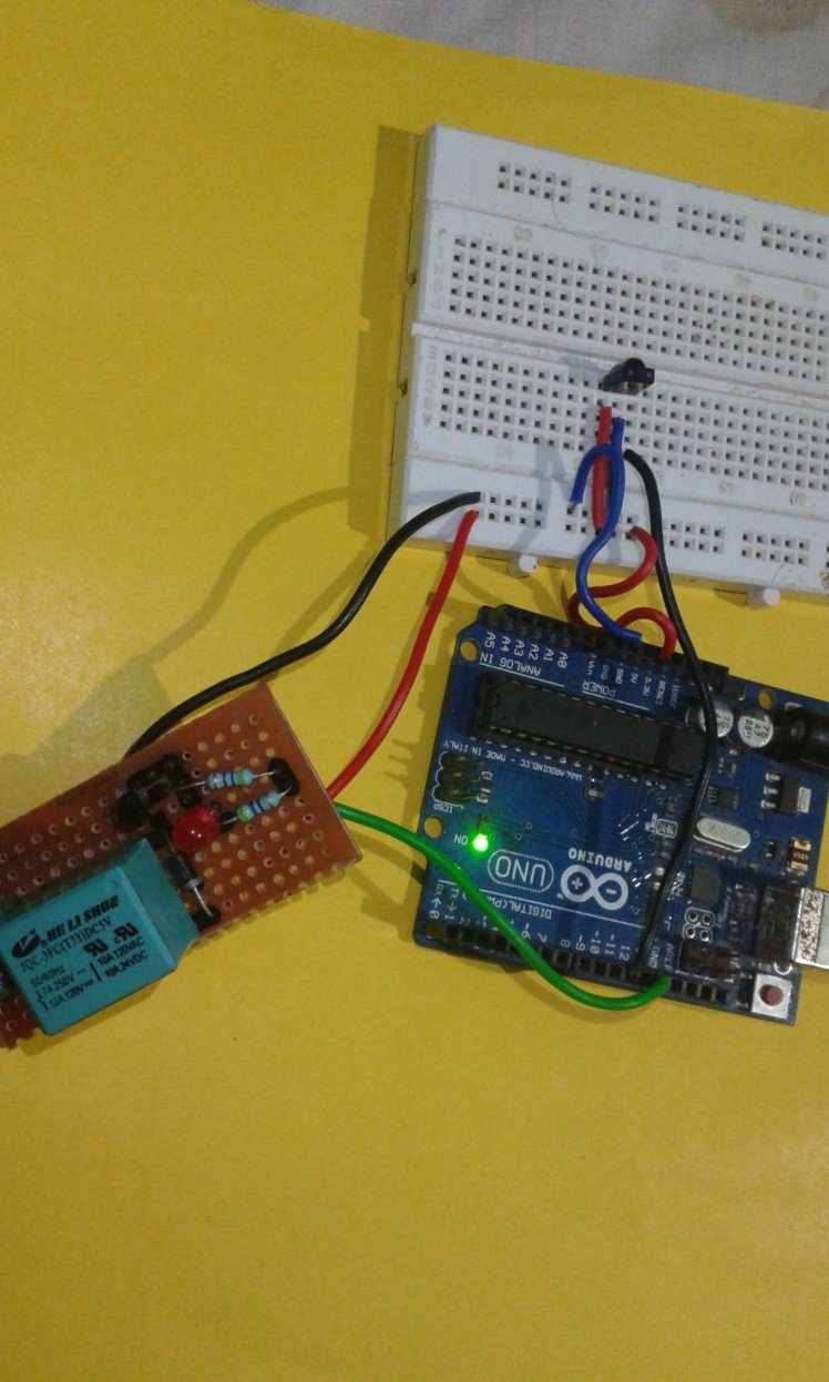
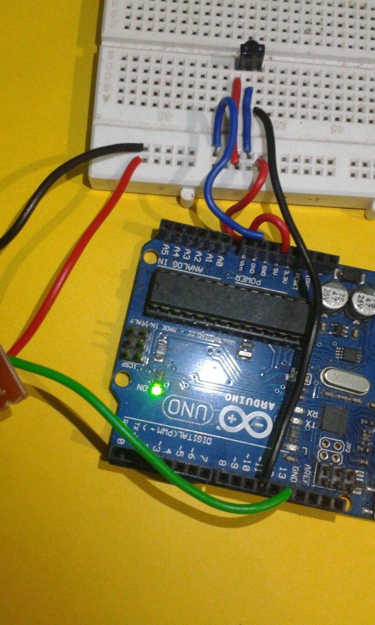
Step 3: The Circuit and Arduino Code
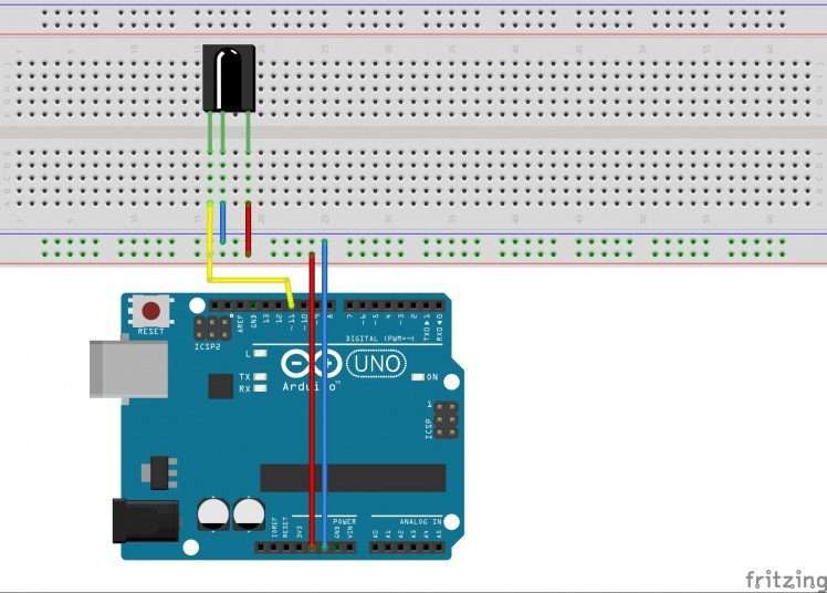
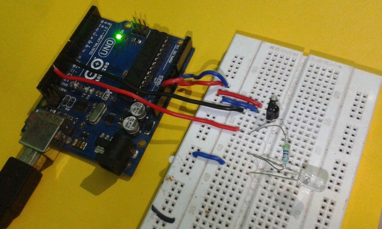
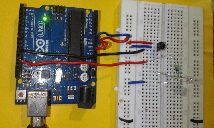
For decoding, we have to setup Arduino Uno with an IR sensor.
Collect these:
- Arduino Uno.
- USB cable.
- Breadboard.
- Jumper wires.
- IR sensor.
Now do the connections as:
- Connect the 5 V of Arduino to the Vcc pin of the IR sensor.
- Connect the GND (Ground) of Arduino to the GND of the IR sensor.
- Connect pin 11 of the Arduino to the IR pin/ the OUTPUT pin of the IR sensor.
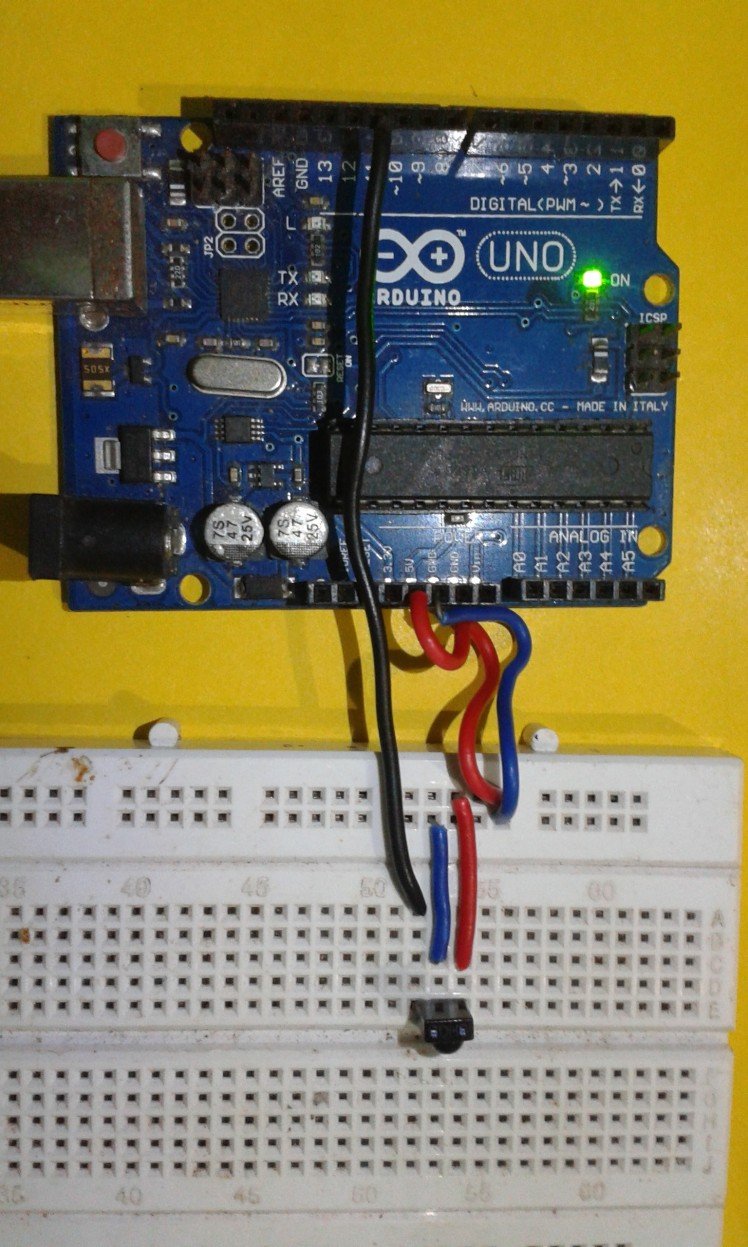
Now the hardware connections are ready.
Before programming, download the IR library attached to this step, unzip the folder and copy the IR library to the libraries folder of the Arduino main folder. (C:Program Files (x86)Arduinolibraries).
Then open the Arduini IDE, copy the code attached here and upload it to the Arduino Uno.
Step 4: Decoding and Recording.
All the circuit and IDE setups are ready, it is the time for decoding now.
Open the "Serial monitor" in the Arduino IDE on your computer.(Tools-Serial monitor). Press the button on the remote controller to the IR sensor on the breadboard. When pressing each button, you can see a unique code in the serial monitor.
Press each button and write down the code.
eg:
Button Code
Play/Pause ---------0x1FE50AF
Next ------------------0x1FE35AC
VOL +----------------0x1FE23DE
1 ----------------------0x1FEA34E
Step 5: Part2: Application 1- Control an LED
Application 1 explains how the remote controller can be used to control an LED or to turn on and off an LED.
For this, a simple addition has to be done with the circuit/breadboard. Connect an LED to the pin number 13 of the Arduino. Do not forget to add a 470 Ohms resistor in series with the LED.
Now upload the code attached to this step to the Arduino Uno, and before uploading, you have to edit the program according to the decoded values of the remote controller. First, decide which buttons of the remote controller have to be used for turning ON and OFF.
In the 39th line of the code, there is "if(results.value==0x1FE50AF)"
here you can replace 0x1FE50AF with the code of the button you wish to turn ON the LED.
And in the 47th line, there is else "if(results.value==0x1FED827)"
Delete 0x1FED827 and add the code of the button you wish to turn OFF the LED.
The remote controller I decoded has "0x1FE50AF" for the button "1" and "0x1FED827" for the button "2". So I am using the buttons 1 and 2 of the remote controller for turning on and off the LED respectively.
After uploading the code you can simply turn on and off the LED connected to the pin number 13.
Step 6: Part 3: Application 2- Control Any AC Device Using Relay Circuit
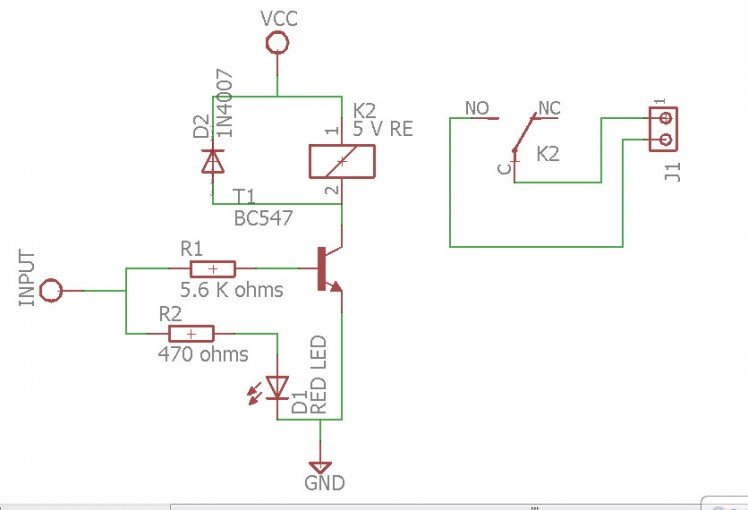
Application 2 looks forward to control a relay circuit connected to the pin number 13 of the Arduino.
For that, we have to make a relay circuit in addition to the previous circuit setup.
Things needed:
- 5 V DC Relay.
- BC 547 Transistor.
- Resistors-4.7 KOhms and 470 Ohms.
- 1N 4007 Diode.
- Terminal connector.
- Wires.
- Perf board.
- LED.
Relay circuit is used to control a circuit with high current/power using the circuit with a low current.
Here, the Arduino pin turns on and off the LED has only 20 milliAmperes of current. We cannot control/turn on and off a high power rated device( like a 230 V light ) with this output. so we use a relay circuit which is nothing but an electromagnetic circuitry.
From the circuit diagram, we can see that the control signal from the Arduino is connected to the base of the BC 547 transistor through a resistor. When a signal is reached to the base of the transistor, it turns the relay switch closed hence turning on the device connected.
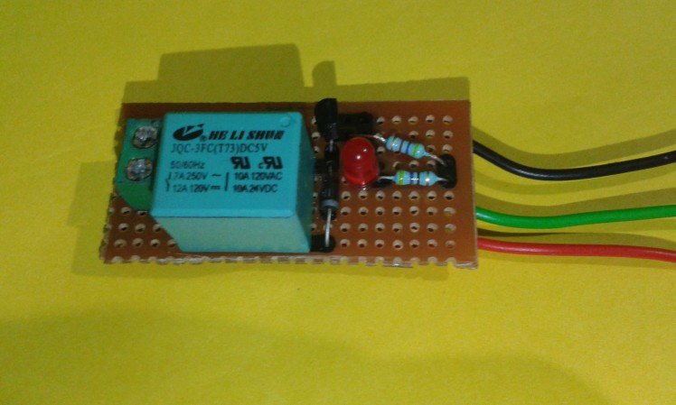
Step 7: Make the Relay
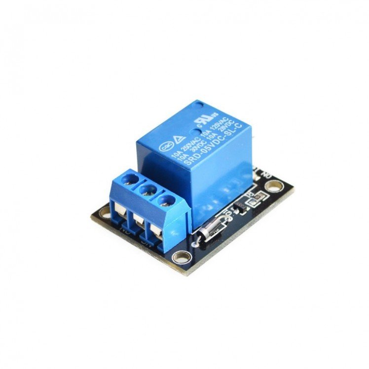
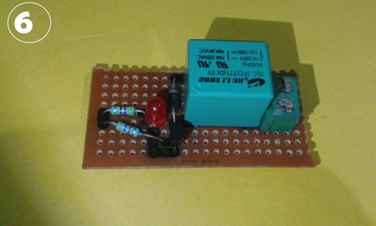
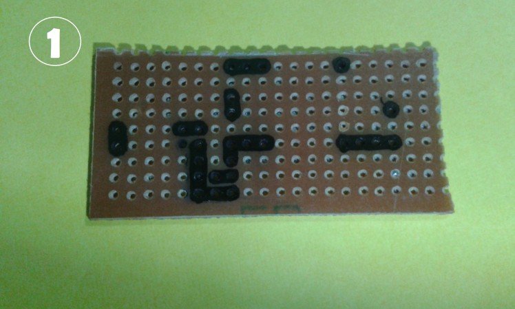
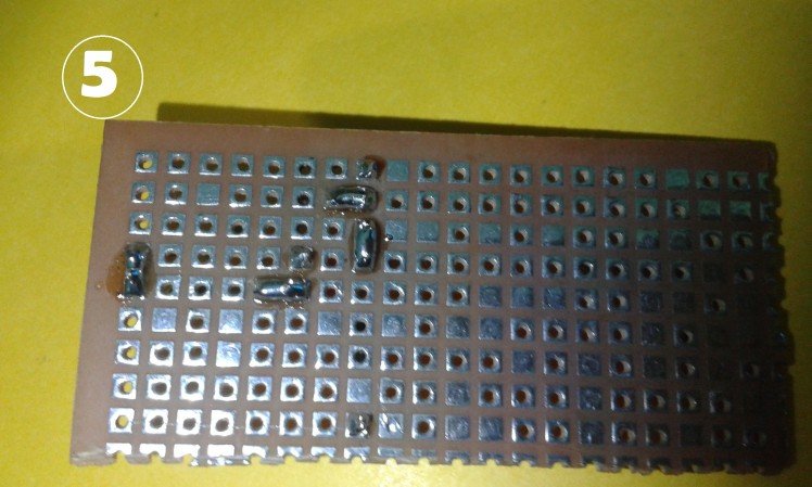
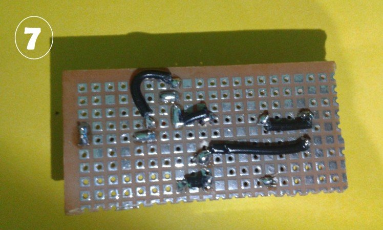
You can buy a relay board (here) or make one yourself following these simple steps:
To do this circuit on the board, we need to:
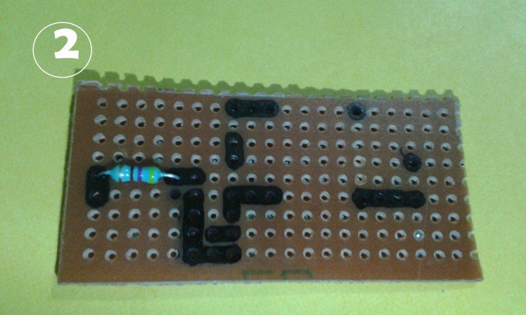
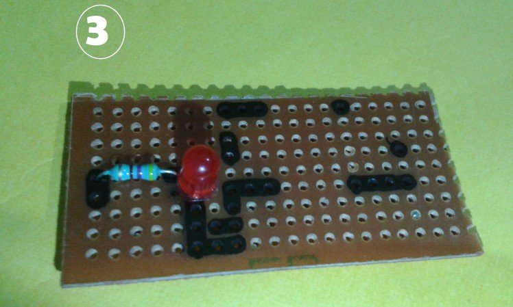
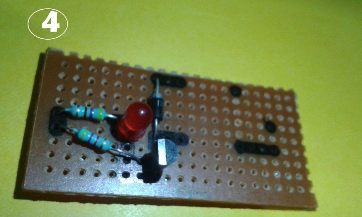
- Cut a piece of perf board.Mark on the board as shown in the picturesSolder the 470 ohms resistor as shown and the LED.
- Solder the 547 transistor.
- Solder the 4.7 Kohms resistor with one led to the input end and the other to the middle pin of the transistor.
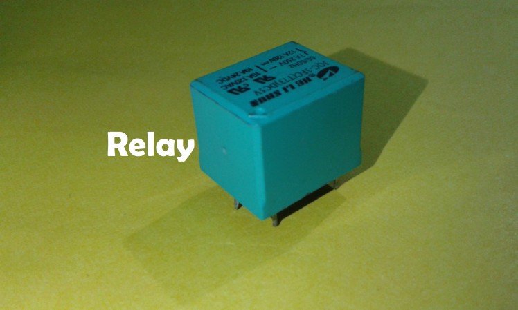
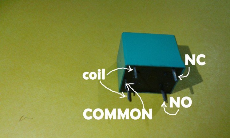
- Solder the relay. Connect one end of the coil to the collector pin of the 547 transistor and leave the other end free.
- Solder the diode across the relay as shown.
- Solder a 2 pin terminal connector near the relay.
- Now joint the resistor ends for the input signal.
- Joint the negative pin of the LED and emitter pin of the transistor.
- Connect the common pin and the NO pins of the relay to the terminal connector.
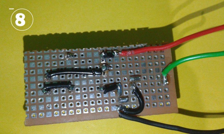
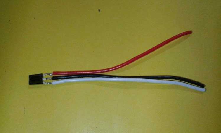
- Now we have to take 3 wires out.
- Solder a red wire to the one end of the relay coil (the one we left). This is the Vcc.
- Solder a black wire to the point where emitter pin of the transistor and negative of the led meets. This is the Ground.
- Solder one more wire to the point where both the resistors meet (the signal wire).
- Strictly follow the steps and the pictures attached.
Refer this instructable for more information about the relay and making a relay.
Step 8: Setup the Circuit
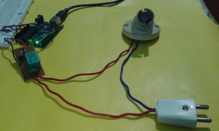
- Now, connect the positive wire of the relay module to the 5 v pin of the Arduino.
- Connect the negative wire of the relay module to the GND pin of the Arduino.
- Then, connect the signal input wire of the relay module to the pin number 13 of the Arduino.
Now, when using the remote controller, you can simply turn on and off the relay. And any AC devices can be connected to the relay and be controlled.
For controlling an AC bulb:
Take :
- A two pin AC plug.
- A bulb holder. And
- Some Wire.
Connect one wire of the plug to the bulb holder directly and connect the other one through the terminal connector of the relay.
Refer the pictures attached.
We can simply control the device attached to the relay by pressing the buttons on the remote controller.
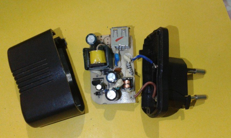
Step 9: Part 4: Application 3- Home Automation Device


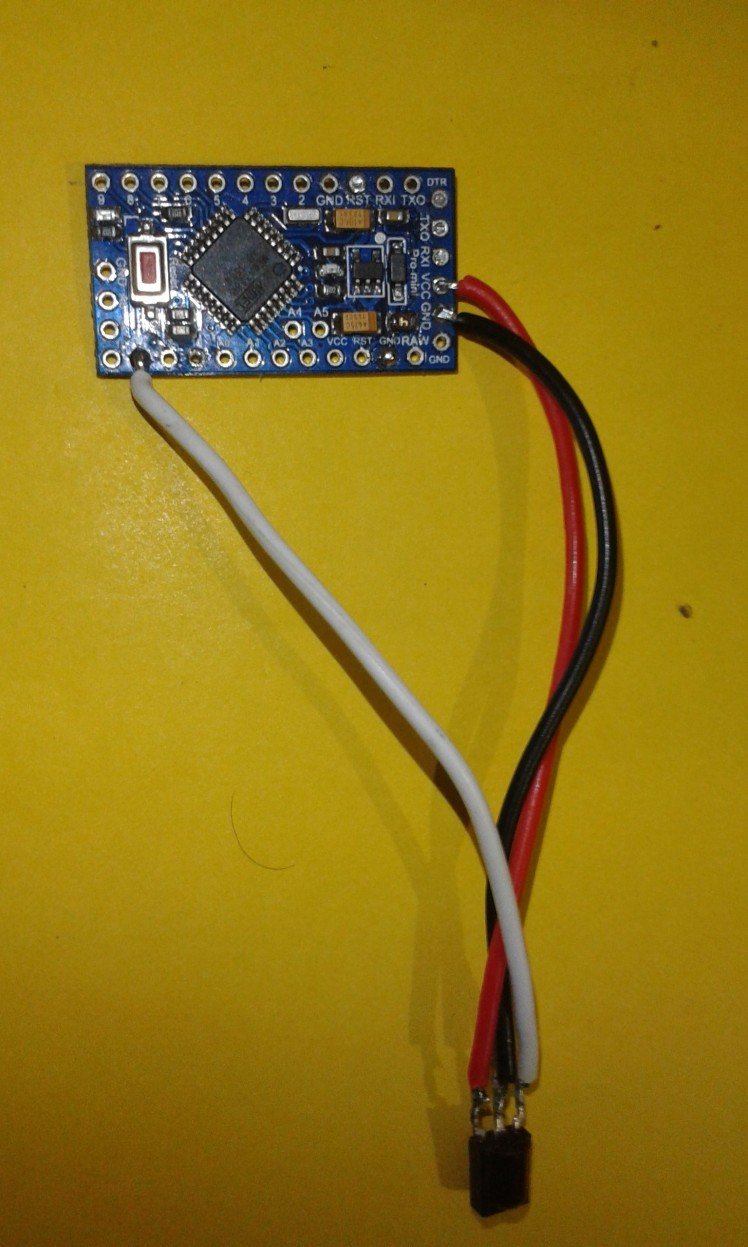
In application 3, we are making a complete IR home automation device. We are using Arduino pro mini instead of Arduino Uno. Pro mini is smaller and handy than Uno. And for the power supply, we are using an old 5 V DC mobile phone charger.
So, we need:
- Arduino Uno.
- Arduino pro mini.
- Wires.
- Relay module.
- An old charger (5 V DC).
- IR sensor.
- Two pin AC plug.
- Plastic enclosure.
- Bulb holder for AC bulb.
Step 10: Programming the Pro Mini
Arduino pro mini can be programmed using Arduino Uno.
- Remove the ATMega 328 microcontroller from the Arduino Uno board.
- Now connect the Rx pin of Arduino pro mini to the Rx pin of Uno.
- Connect Tx pin of the Arduino pro mini to the Tx pin of the Uno.
- Connect Vcc and GND of the pro mini to that 5V and GND pins of Uno respectively.
- Connect the RESET pin of the pro mini to the RESET pin of the Uno.
- Then, in Arduino IDE, select Tools-- Board-- Arduino pro/pro mini.
- And finally, upload the same code to the board.
Refer this instructable for a more detailed explanation.
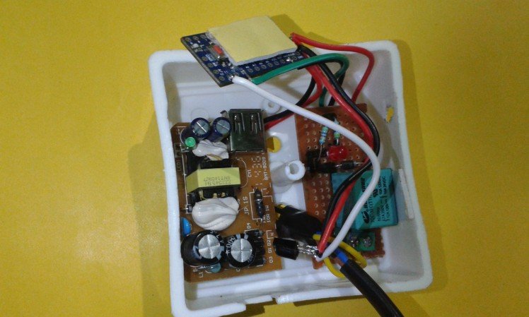
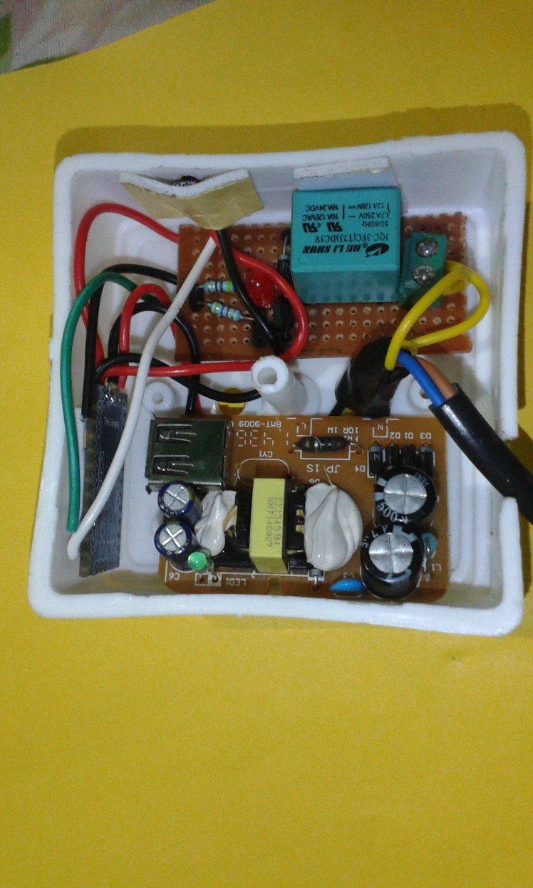
Step 11: Connect Them Together.
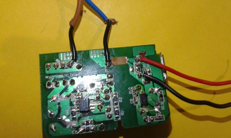
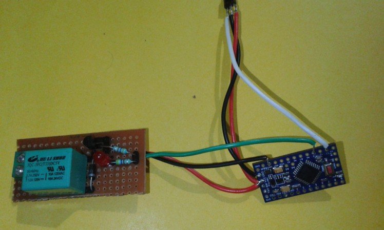
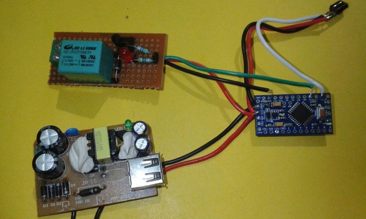
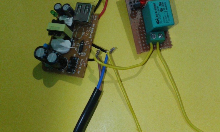
Now we have to connect all the parts together including the pro mini, the relay board, IR sensor and the power supply board.
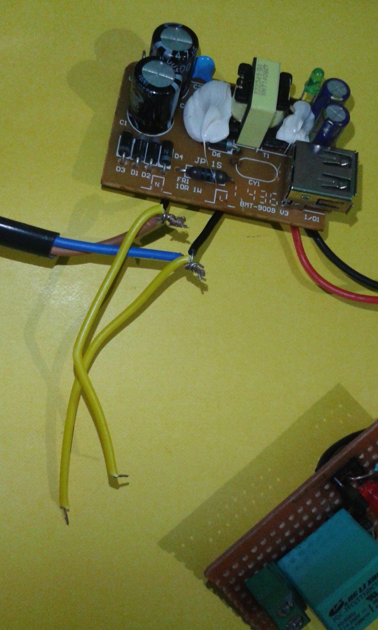
- Open the charger and take the board out.
- Solder the wire for the AC supply.
- Soder the wires for 5 V DC output.(Vcc and GND).(Red and black)
- Now, take the pro mini and solder the output wires of the power supply board to the pro mini.
- Take the IR sensor and solder it's Vcc and GND to the Vcc and GND of pro mini. Solder its output pin(IR pin) to the pin number 11 of pro mini.
- Take the relay and solder its Vcc and GND to the Vcc and GND of pro mini. Solder its signal wire to the pin number 13 of pro mini.
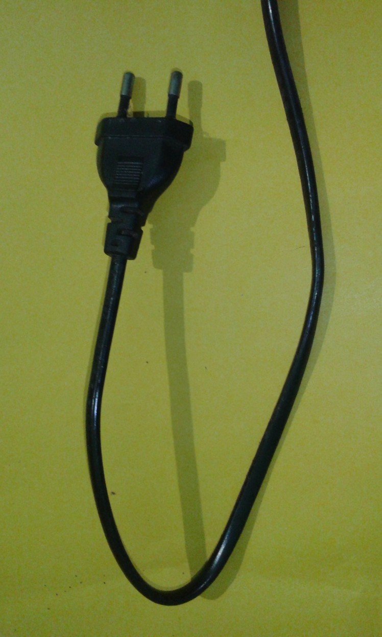
- Solder the AC plug to the power supply board.
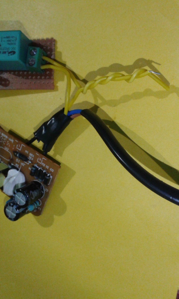
- Now join two more wires to the power supply plug(Yellow wires).
- Out of the two wires, connect one to the terminal connector of the relay and leave the other one free.
- Take a wire and connect it to the other point of the terminal connector. Twist this wire and the yellow wire from the power supply together forming a twisted yellow wire.
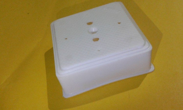
Step 12: The Box Enclosure.
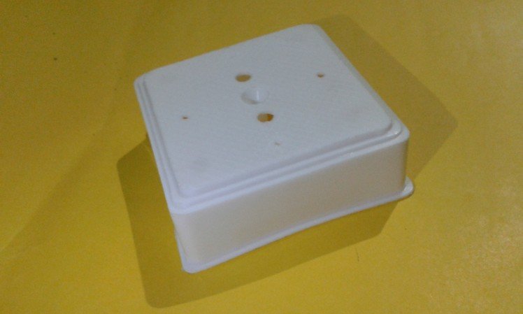
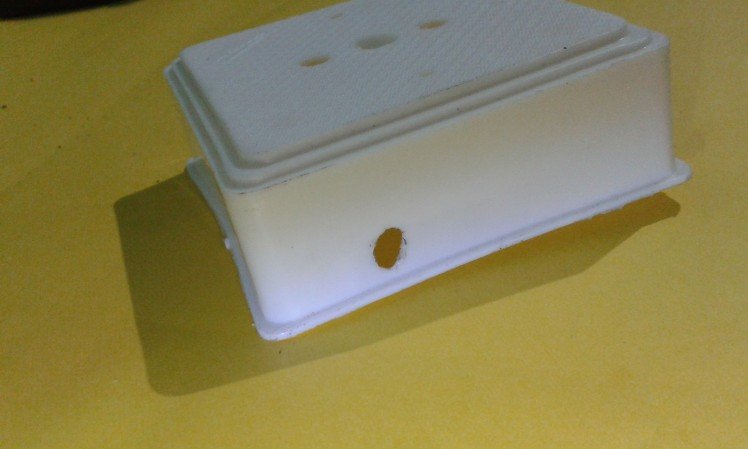
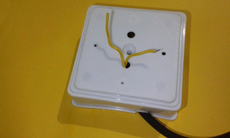
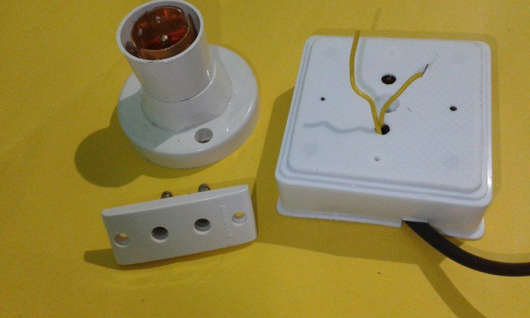
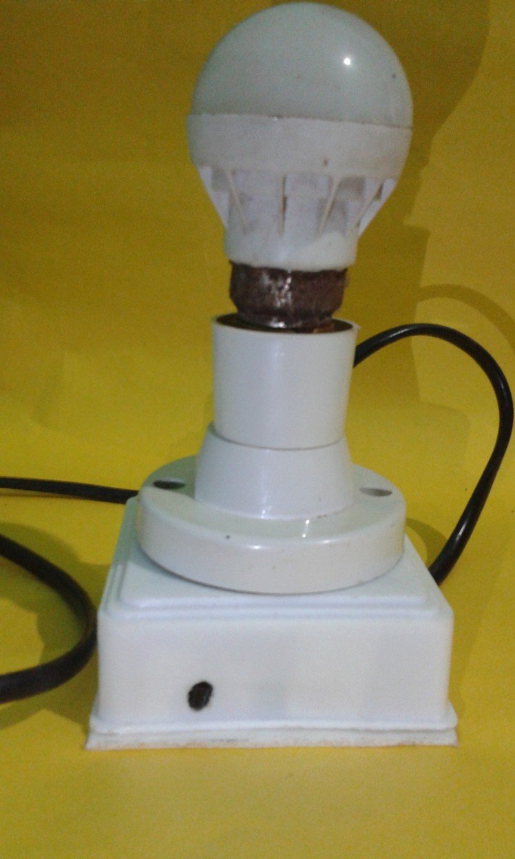
For making the enclosure, take the plastic box and make a tiny hole for the IR sensor. Fix the IR sensor near the hole facing out the box. Place all the boards inside the box and fix it there using double-sided tape. Take the yellow twisted pair wire out and close the box.
Connect the yellow wires to the bulb holder and fix the holder on the box.
Instead of the bulb holder, one can use the two pin socket on the box so that we can control any AC device connected.
After this step, all the setup is ready and you can plug it into the ac outlet and control the bulb using the remote controller.
Step 13: Thank You.
Hope you all enjoyed and well-understood this how to. Feel free to use the comment box and try to make it.
Happy making.
Vote for me in the remote control contest if you like this.
Thank you...
Credits
Related products


Leave your feedback...