
Internet Connected Infrared Replicator

Made by gusgonnet
About the project
Decode and replicate plenty of IR remotes with this project. (Problems with your Harmony remote anyone?)
Items used in this project
Hardware components


View all
Story
Some time ago I got into decoding an infrared AC remote with the purpose of controlling an air conditioner via WIFI.
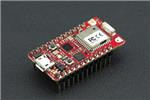
I learned a ton of things along the way and I wanted to share that knowledge with all of you in case it can help you in future projects (future-me: I'm looking at you too). I used a Particle Photon but you may choose to use a different MCU since the IRremote Arduino Library (from Ken Shirriff) used in this project supports plenty of others. Here's also its official page.
There is a lot of information on that page, make sure to read some of it for a deep understanding of how IR signals work, but I'll reproduce some important points in the next section.
Some background on IR codes
The following is a transcription of the author's original post:
An IR remote works by turning the LED on and off in a particular pattern. However, to prevent interference from IR sources such as sunlight or lights, the LED is not turned on steadily, but is turned on and off at a modulation frequency (typically 36, 38, or 40KHz). The time when a modulated signal is being sent will be called a mark, and when the LED is off will be called a space.
Each key on the remote has a particular code (typically 12 to 32 bits) associated with it, and broadcasts this code when the key is pressed. If the key is held down, the remote usually repeatedly broadcasts the key code. For an NEC remote, a special repeat code is sent as the key is held down, rather than repeatedly sending the code. For Philips RC5 or RC6 remotes, a bit in the code is toggled each time a key is pressed; the receiver uses this toggle bit to determine when a key is pressed down a second time.
On the receiving end, the IR detector demodulates this signal, and outputs a logic-level signal indicating if it is receiving a signal or not. The IR detector will work best when its frequency matches the sender's frequency, but in practice it doesn't matter a whole lot.
You are now ready for the next step...
Build the IR receiver circuit
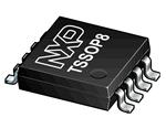
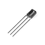
In order to decode infrared signals, you need an infrared receiver diode:
 IR receiver diode
And you build the receiver circuit as stated in the library:
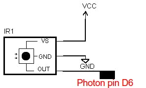 Receiver circuit
Here's the pinout:
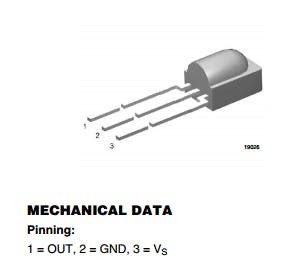 Source: https://www.sparkfun.com/datasheets/Sensors/Infrared/tsop382.pdf
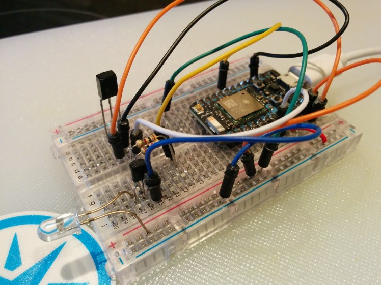
My breadboard ended up looking like this:
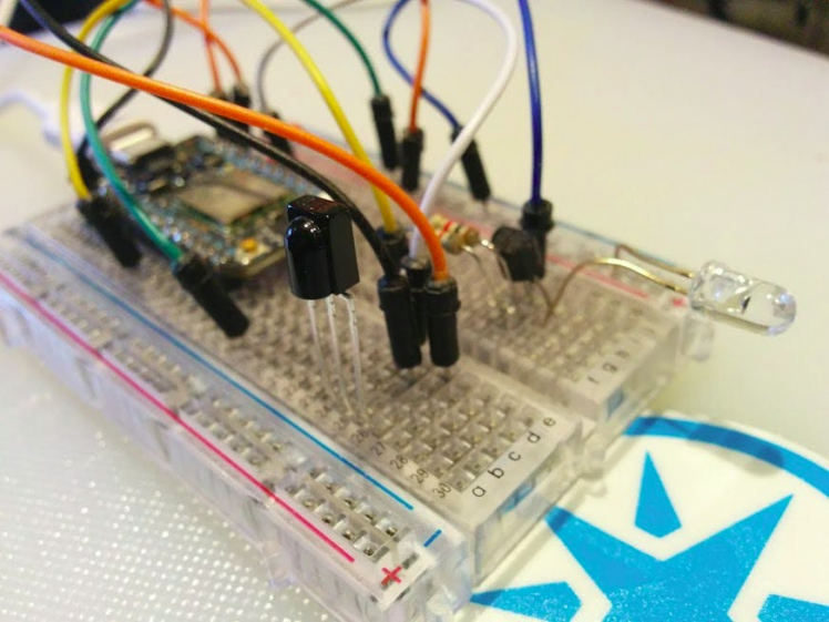 My implementation on a breadboard
For now, focus on connecting the receiver diode (the black one) and forget about the transmitter (the transparent one) - we will take care of it later.
Decode some IR signals
Since the project will dump the received codes via the serial line, we need to connect it to a computer. Power up the Photon with an USB cable and connect it to an USB port of your computer. Now will be a very good time to flash the attached firmware.
Open a console or terminal, and use the Particle CLI to monitor the USB port.
NOTE: If you don't have the Particle CLI installed, please do so by following the docs here.
In Ubuntu Linux, this is what I had to type to monitor the serial port of the Photon:
$ sudo chmod 666 /dev/ttyACM0
$ particle serial monitor
Depending on your computer and operating system, the port might have a different name and/or the chmod might not need to be executed.
NOTE: you can use any other software to receive data on the USB serial port of your computer.
Having done that, you can point the remote you want to decode to the IR receiver diode (the black LED-alike component) Start hitting buttons on it and check what is printed in the console.
If all goes well you will be getting something like this:
1FEA05F
29168950,8500,4050,500,1500,550,500,550,450,550,500,500,1550,500,500,550,500,500,500,550,500,500,500,550,450,550,500,550,1500,500,500,550,500,500,500,550,500,500,550,500,1500,550,1500,550,450,550,1500,550,500,500,1500,550,500,550,450,550,500,500,500,550,END
3,3,2,0,1,0,0,0,0,0,0,0,1,0,0,0,0,0,0,0,0,0,0,0,0,0,0,0,1,0,0,0,0,0,0,0,0,0,0,0,1,0,1,0,0,0,1,0,0,0,1,0,0,0,0,0,0,0,0,0,END
- First line (1FEA05F) and third line: forget about them for now
- Second line: this line prints the IR command sent by the remote
Our first decoded IR command
Let's talk about the received IR command:
29168950,8500,4050,500,1500,550,500,550,450,550,500,500,1550,500,500,550,500,500,500,550,500,500,500,550,450,550,500,550,1500,500,500,550,500,500,500,550,500,500,550,500,1500,550,1500,550,450,550,1500,550,500,500,1500,550,500,550,450,550,500,500,500,550,END
We can discard the first value, 29168950 in this case, since the IR library states the following: "the receive buffer starts with the duration of the gap space before the first mark". We don't care about that duration, since is the time that passed by in between our tests, or the time it took you to hit a button in the remote.
Hence from the received output this is what is really interesting and what shapes the IR command:
8500,4050,500,1500,550,500,550,450,550,500,500,1550,500,500,550,500,500,500,550,500,500,500,550,450,550,500,550,1500,500,500,550,500,500,500,550,500,500,550,500,1500,550,1500,550,450,550,1500,550,500,500,1500,550,500,550,450,550,500,500,500,550,END
Those numbers represent the duration of the infrared pulses in microseconds. If we wanted, we could send this command with the following code:
function sendIt() {
  unsigned int ircommand[59]={8550,4000,550,1500,550,450,550,500,500,550,500,1550,500,500,500,500,550,500,500,500,550,500,500,500,550,500,500,1500,550,500,500,500,550,500,500,500,550,450,550,1500,550,1500,550,500,500,1500,550,500,550,1500,500,500,550,500,500,500,550,450,550};
  irsend.sendRaw(ircommand,59,38);
}
But for that, we will need to build the transmitter circuit. Let's do that next.
Build the IR transmitter circuit
The simplest circuit looks like this:
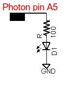
However this circuit will only give you less than a meter of range.
If you can, wire a circuit like this one below for an improved range (around 10 meters):
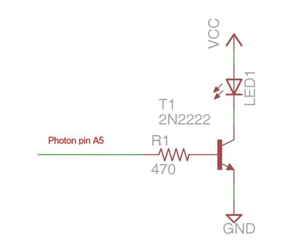 Source: https://learn.adafruit.com/using-an-infrared-library/sending-ir-codes
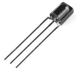
This is the transmitter side of my circuit:
 IR transmitter LED (the transparent one)
Testing the IR transmitter circuit
I've added a couple of functions in the firmware to control the volume on a Samsung TV. This is so you can test if your transmitter circuit is working in the case you have a Samsung TV around.
Just point your transmitter LED to your TV and hit on the functions sendSamsungVolumeUp() and sendSamsungVolumeDown().
NOTE: Remember that you can use your cell phone camera to check whether the IR LED is transmitting, since IR shows up there:
Source: https://commons.wikimedia.org/wiki/File:Remote_control_infrared_animated.gifMaking the IR commands more readable
If we identify values around 500 with a 0 and 1500 with a 1, this selection being arbitrary, also assigning 3 to values over 5000 and 2 to values around 4000, we end up with the following representation:
3,3,2,0,1,0,0,0,0,0,0,0,1,0,0,0,0,0,0,0,0,0,0,0,0,0,0,0,1,0,0,0,0,0,0,0,0,0,0,0,1,0,1,0,0,0,1,0,0,0,1,0,0,0,0,0,0,0,0,0,END
Now remember that in this totally arbitrary encoding:
- 3 means an 8500 microseconds pulse
- 2 means a 4000 microseconds pulse
- 1 means a 1500 microseconds pulse
- 0 means a 500 microseconds pulse
Why encoding in numbers, you may ask?
It helps visualizing and comparing commands, I hope. This way, it becomes easier to compare pulses that change or remain the same among different commands.
Example: you want to compare what changes between a command to set the temperature to 18 and 19 degrees in the case of an AC remote control? Easier when you have 1's and 0's.
I also like this format for storing the IR commands in the firmware code. Just remember to convert them to pulses right before transmitting (by calling the function convertToPulseDuration() in the firmware).
Reading resources
I read a bunch of sites to be able to understand the topic. Here's a list of some of them:
Conclusion
With some work, an MCU and a couple of components you will be able decode and replicate many of the remotes you have around your house. With some limitations, this can allow you to control all those devices from your phone, tablet, laptop, computer, and even create some simple automations for them. Cool, huh?
 Other uses may include replacing/complementing a Harmony remote control
Now you can think about adding Blynk, creating an app in the Ionic Framework, talking to it with Google Now or Alexa, or controlling it with Porter.
I'm planning on applying this knowledge to control few devices around the house, and I'm hoping to create more write-ups in the future. Stay tuned!
Update on Feb 5th 2018:
Here's one implementation of this project: an infrared fireplace controlled from the internet.
Need help?
If you require professional help with your projects, don't hesitate to write me a line about your needs at gusgonnet@gmail.com. Thank you!
Schematics, diagrams and documents
Code
Credits
Related products


Leave your feedback...