
Internal Timers Of Arduino

Made by electrouser809 / Clocks
About the project
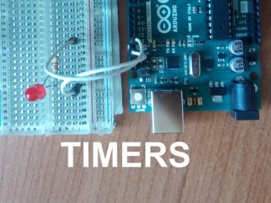
In this tutorial I will explain how to use the TIMER0 of Arduino
Project info
Difficulty: Moderate
Platforms: Arduino
Estimated time: 1 hour
License: GNU General Public License, version 3 or later (GPL3+)
Items used in this project
Hardware components


Story
Overview
If you need to count accurate time you need to use a timer, but usually it isn't so easy to use the internal timers of Arduino, so in this tutorial I try to explain how to use them in an easy way.
It is so important to use timers because during the delay() function you can't do anything, but with a timer you can do everything because when the moment does arrive, it activates the interrupt.
I use the TIMER0 because it is the easiest timer, maybe in the future I may explain the other timers.
How It Works
The first thing you need to see is the datasheet of ATmega328P.
 COUNTER BLOCK DIAGRAM
This is the counter block diagram, and looking at this you can understand how it works.
The prescaler receives a pulse from a clock cycle and then passes it to the Control Logic, therefore the Control Logic increments the TCNTn register by 1.
Now we can compare the value of TCNTn with a specific value. When the TCNTn register arrives at this value, you know that it is passed a specific time.
This method is called CTC mode for "Clear Timer on Compare". The value TCNTn register is compared to the OCRn register, when a compare match occurs the TOVn generates an interrupt.
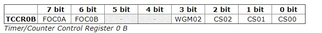
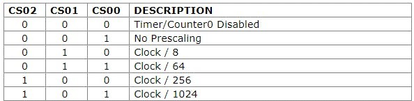
Another important thing is the prescaler, with this you can create different divisions of the clock, in fact 16MHz is too much but, thanks to the prescaler, you can create some submultiples of it. This depends on the configuration of the TCCR0B register.
Another important thing is determine the value of OCRn register to count a specific time, you need a bit of math.
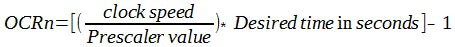
I know that all of this can seem too complicated but I'm sure that the code below will clear up each question.
In this case, we activate an interrupt request each 0.001 seconds.
 TCCR0A|=(1<<WGM01); //Set the CTC mode
 OCR0A=0xF9; //Set the value for 1ms
 TIMSK0|=(1<<OCIE0A); //Set the interrupt request
 sei(); //Enable interrupt
 TCCR0B|=(1<<CS01); //Set the prescale 1/64 clock
 TCCR0B|=(1<<CS00);
ISR(TIMER0_COMPA_vect){ //This is the interrupt request
}
It is important to set the prescaler at the end because after this instruction the timer starts to count, if you need to stop it, you must reset all the bits of TCCR0B.
Below there is an example.
Schematics, diagrams and documents
Code
Credits
Related products


Leave your feedback...