





Interfacing 16×2 Lcd With Arduino Uno

Made by play-with-circuit / Home Automation
About the project
In this guide, we will connect a 16×2 LCD module with an Arduino Uno in 8-bit mode and 4-bit mode.
Project info
Difficulty: Easy
Platforms: Arduino
Estimated time: 1 hour
License: GNU General Public License, version 3 or later (GPL3+)
Items used in this project
Hardware components


Story
Character LCD displays are still one of the simplest and most practical ways to show text in embedded projects. Whether you are building a sensor dashboard, home automation system, or robotics project, a 16×2 LCD can instantly make your setup more interactive by displaying live readings, menu options, or system messages.
In this guide, we will explore how to connect a 16×2 LCD module with an Arduino Uno in 8-bit mode and 4-bit mode. We will also see how to create and display custom characters for more personalized outputs.
What is a 16×2 LCD Module?
A 16×2 LCD is a character display module capable of showing 16 characters per line across two rows. These displays are widely used in Arduino and embedded applications because they are affordable, easy to interface, and consume very little power.
The module is based on the popular HD44780 controller, which supports multiple communication modes and allows users to display letters, numbers, symbols, and even custom-designed characters.
16×2 LCD Pinout Diagram
A standard 16×2 LCD usually comes with 16 pins. These pins are used for power, contrast adjustment, control signals, and data transfer.
Important pins include:
- VSS and VDD for ground and power supply
- VO for contrast control using a potentiometer
- RS for selecting command or data mode
- RW for read/write operation
- E for enabling data transfer
- D0–D7 data pins
- A and K for LCD backlight
In most Arduino projects, the RW pin is connected directly to ground since writing to the display is more common than reading from it.
Interfacing LCD with Arduino in 8-bit M
ode
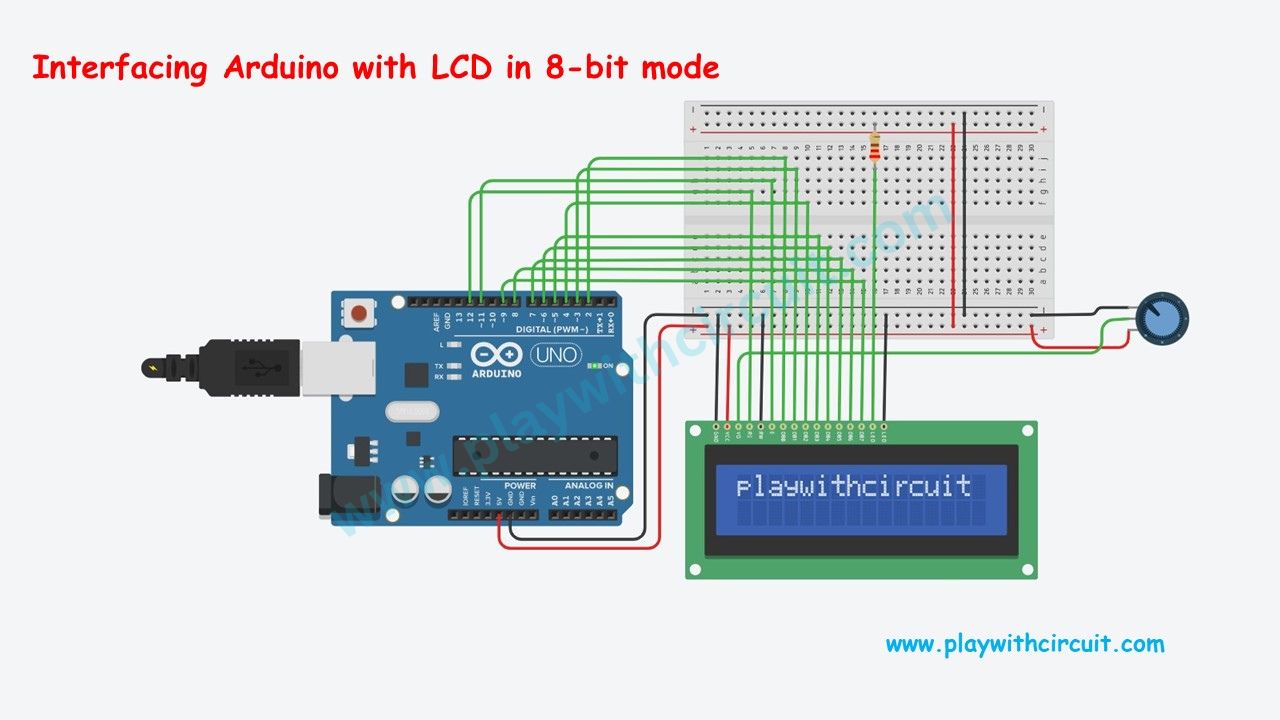
In 8-bit mode, all eight data pins of the LCD are connected to the Arduino. This method provides faster communication because the full byte is transferred at once. However, it also consumes more GPIO pins.
This mode is useful when speed matters and enough I/O pins are available.
Basic Connection Overview
- LCD data pins D0–D7 connect to Arduino digital pins
- RS and Enable pins connect to Arduino control pins
- Contrast is adjusted using a 10k potentiometer
- Backlight pins connect to power and ground
After wiring the circuit, the Arduino LiquidCrystal library can be used to initialize the display and print messages.
Why Use 8-bit Mode?
- Faster data transfer
- Easier to understand for beginners learning LCD internals
- Suitable for larger embedded systems with sufficient GPIO pins
The downside is increased wiring complexity.
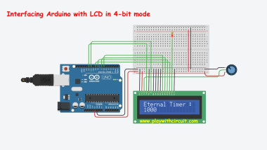
Interfacing LCD with Arduino in 4-bit Mode
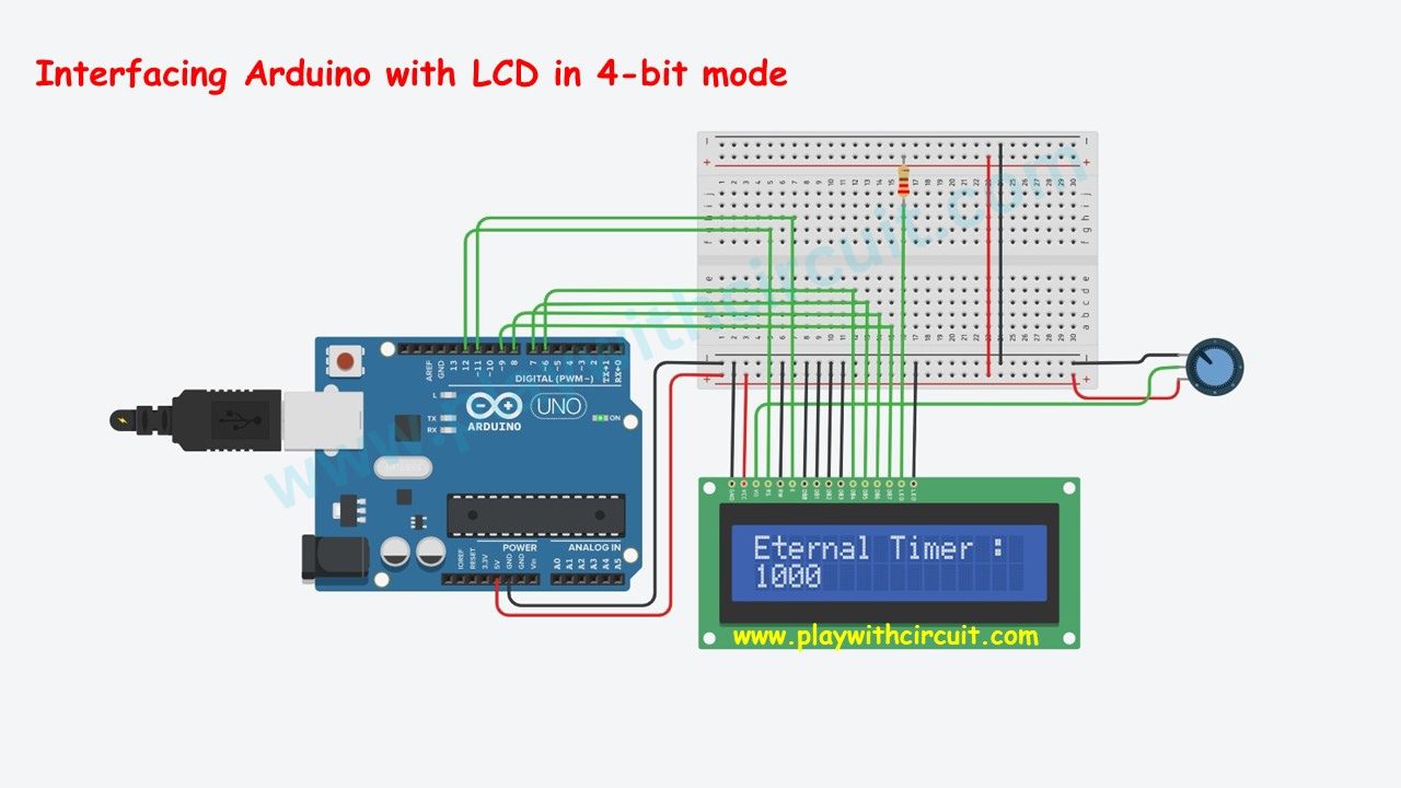
4-bit mode is the most commonly used configuration because it reduces the number of Arduino pins required. Instead of using all eight data lines, only four are used to send data in two parts.
This approach saves GPIO pins for other sensors and modules while still providing reliable LCD communication.
Display Custom Character on LCD
One interesting feature of the HD44780 LCD controller is the ability to create custom characters. This allows you to display icons, symbols, battery indicators, arrows, emojis, or animated effects.
Custom patterns are stored in the LCD’s CGRAM memory using binary pixel maps.
For example, you can create:
- Heart symbols
- Smiley faces
- Battery indicators
- Loading animations
- Sensor status icons
This feature is especially useful in interactive embedded interfaces where graphical feedback improves usability. The 16×2 LCD remains one of the most beginner-friendly display modules for Arduino and embedded electronics. Whether you use traditional 8-bit communication, space-saving 4-bit mode, or a modern I2C interface, the module offers a reliable way to display project data in real time. For hobbyists and students, it is also an excellent way to learn how embedded systems handle communication between microcontrollers and peripherals. If you want the full wiring details, Arduino code examples, and deeper explanations, visit the original tutorial at Play with Circuit.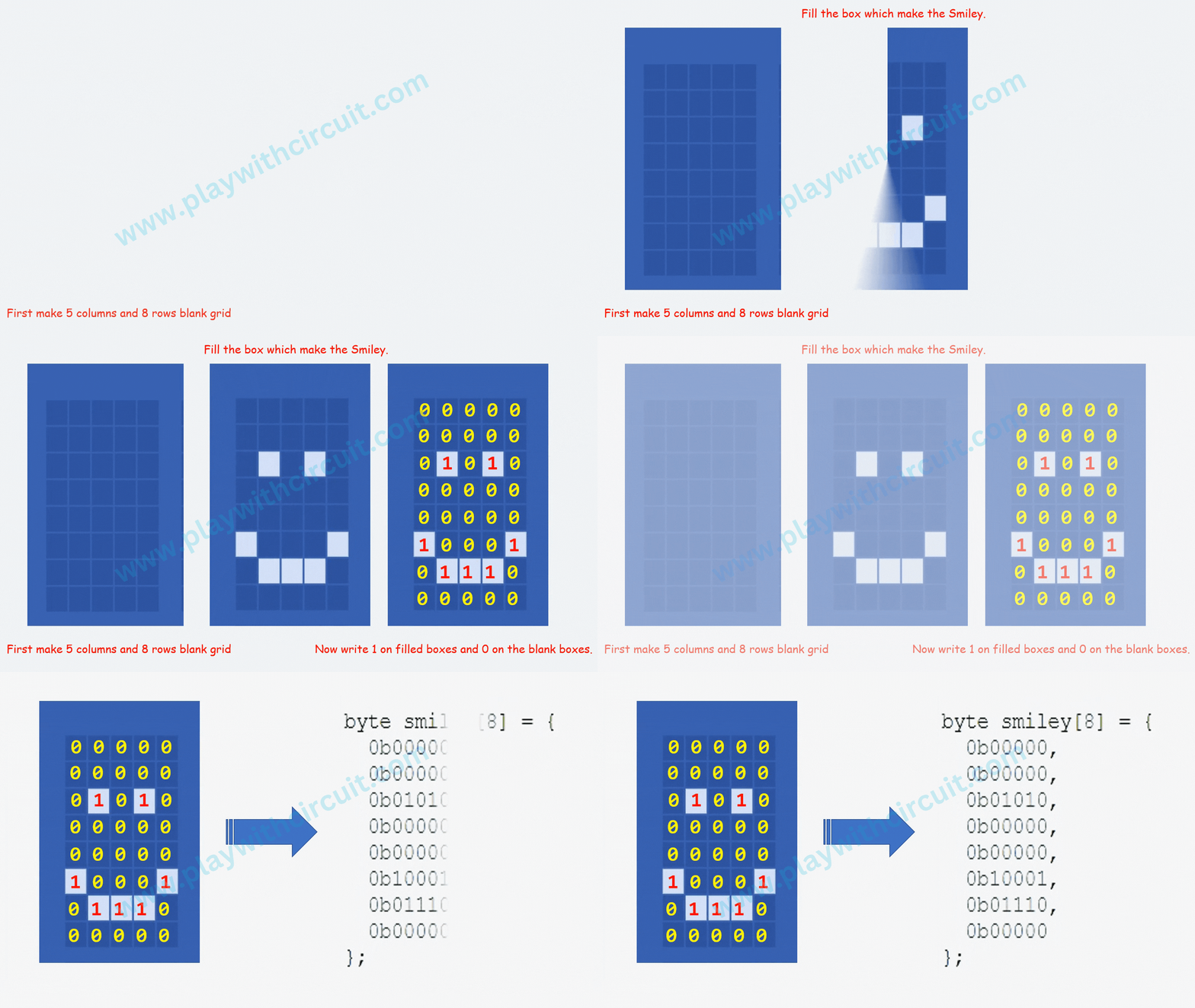
Final Thoughts
Credits
Related products





Leave your feedback...