

Implement Freertos With Arduino Ide On Esp32

Made by Makerfabs01
About the project
In this time, we will implement FreeRTOS with Arduino IDE On ESP32 TFT touch screen. You will learn 2 simple FreeRTOS demos.
Project info
Difficulty: Easy
Platforms: Arduino
Estimated time: 2 hours
License: GNU General Public License, version 3 or later (GPL3+)
Items used in this project
Hardware components

Story
A Real-Time Operating System(RTOS) is intended to fulfill the requirements of real-time applications. It processes data as comes in, typically without buffering delays. There aremany famous RTOS such as the LynxOS, RTLinux, VxWorks, FreeRTOS, OSE, QNX, Windows CE, which intend to different applications. Of these RTOS, FreeRTOS is specially designed for microcontrollers, because Microcontrollers come with limited resources, therefore, we need an operating system as per the available resources of microcontrollers. FreeRTOS an open-source Kernel which means it can download free of cost and be used in RTOS-based applications.
Lucky that the ESP32 and Arduino IDE support the FreeROTS well. When we write small-size embedded software for Arduino we do not need any ROTS, but when its complexity and size increases FreeRTOS is always beneficial, by using FreeRTOS, we can make sure that each task of Arduino have a deterministic execution pattern and every task will meet its execution deadline. In other words, it is a scheduler that assigns Arduino CPU resources to every task according to a scheduling algorithm.
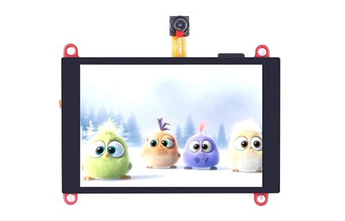
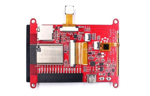
In this article, We will use Arduino IDE to program Makerfabs ESP32 3.5 inch TFT display with FreeRTOS, er, just simple& easy start for learners, and also for myself. This module is based the ESP32 3.5” SPI display with Touch, with plenty of GPIO breakout for external usage, so pretty suitable for this learning.
Arduino IDE:
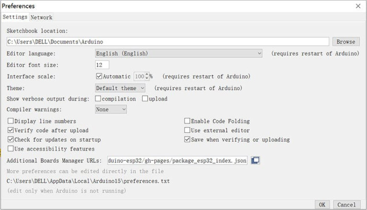
● Download and install the Arduino IDE 1.8.19;● Install the ESP32 Library at Fill-->Preference-->Additional Boards Manager URLs: https://raw.githubusercontent.com/espressif/arduino-esp32/gh-pages/package_esp32_index.json
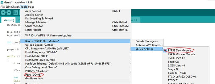
● Then in the Tools--> Board Manager, search the ESP32, and install:
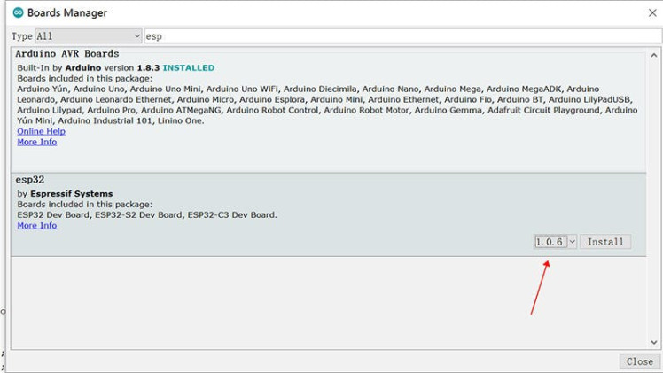
● It should take a few minutes to install it, after installing, you should be able to find the “ESP32 dev module” in Tools->ESP32 Arduino, and also the ports in Tools--> ports.
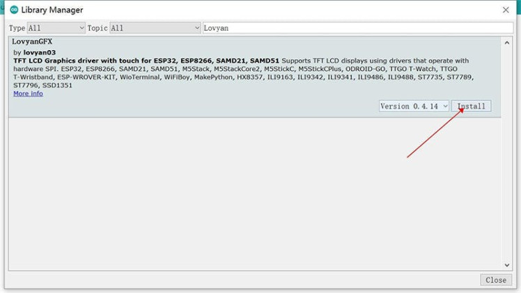
● And finally, download& install the Makerfabs 3.5” inch display library LovyanGFX in Tools--> Library Manager.
FreeRTOS Demo_1
LED controlling is mostly the easiest task for a controller, that we control the LED On/Off by digitalWrite() and delay() to control its On/Off time when we begin to learn to program. But as delay() suspended the controller, in real works, for multiple LED controlling, we use Timers/interrupts to control its On/Off time. When there are multiple LEDs with different controlling modes, this could be complex, and make the whole code not readable.
With FreeRTOS, we can make it clear. In this example, we will control 4 channels LED(A/B/C/D), the A/B act as a breath LED with different frequencies, and C/D act as a simple LED, with different modes. Besides, the 3.5 inch display acts as a Timer, with touch control.
1. In the setup, the xTaskCreatePinnedToCore() was used to create a task:
void setup()
{
    Serial.begin(115200);

    pinMode(LCD_CS, OUTPUT);

    SPI.begin(SPI_SCK, SPI_MISO, SPI_MOSI);

    xTaskCreatePinnedToCore(Task_TFT, "Task_TFT", 4096, NULL, 3, NULL, ARDUINO_RUNNING_CORE);
    xTaskCreatePinnedToCore(Task_Count, "Task_Count", 2048, NULL, 1, NULL, ARDUINO_RUNNING_CORE);
    xTaskCreatePinnedToCore(Task_GPIO_1, "Task_GPIO_1", 2048, NULL, 2, NULL, ARDUINO_RUNNING_CORE);
    xTaskCreatePinnedToCore(Task_GPIO_2, "Task_GPIO_2", 2048, NULL, 2, NULL, ARDUINO_RUNNING_CORE);
    xTaskCreatePinnedToCore(Task_GPIO_3, "Task_GPIO_3", 2048, NULL, 2, NULL, ARDUINO_RUNNING_CORE);
    xTaskCreatePinnedToCore(Task_GPIO_4, "Task_GPIO_4", 2048, NULL, 2, NULL, ARDUINO_RUNNING_CORE);
}
xTaskCreatePinnedToCore(TaskFunction_t pvTaskCode, const char *constpcName, const uint32_t usStackDepth, void *constpvParameters, UBaseType_t uxPriority, TaskHandle_t *constpvCreatedTask, const BaseType_t xCoreID):
Parameters:
pvTaskCode: Pointer to the task entry function.
pcName: A descriptive name for the task, mainly used to facilitate debugging.
usStackDepth: The size of the task stack is specified as the number of bytes.
pvParameters: Pointer that will be used as the parameter for the task being created.
uxPriority: The priority at which the task should run.
pvCreatedTask: Used to pass back a handle by which the created task can be referenced.
xCoreID: Values 0 or 1 indicate the index number of the CPU to which the task should be pinned, ESP32 has 2 cores. Use ARDUINO_RUNNING_CORE by default.
Return:
pdPASS if the task was successfully created and added to a ready list, otherwise an error code is defined in the file projdefs.h
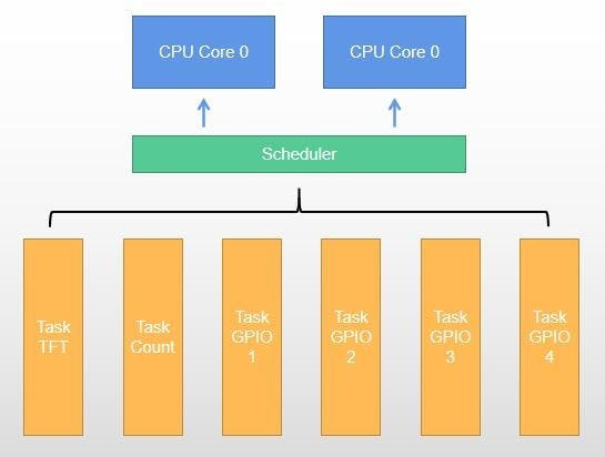
In our codes, there totally 6 tasks were created:
Task_TFT:for the display& Touch;
Task_Count: for counting;
Task_GPIO_1(2/3/4): for 4 LEDs controlling;
2. And in the task definition, we define the task detailed:
void Task_GPIO_1(void *pvParameters)
{
    (void)pvParameters;

    ledcAttachPin(PIN_A, 0); // assign RGB led pins to channels
    ledcSetup(0, 1000, 8);   // 1 kHz PWM, 8-bit resolution

    while (1) // A Task shall never return or exit.
    {
        for (int i = 0; i < 256; i += 16)
        {
            ledcWrite(0, i);
            vTaskDelay(LED_FRESH_TIME);
        }
        for (int i = 255; i >= 0; i -= 16)
        {
            ledcWrite(0, i);
            vTaskDelay(LED_FRESH_TIME);
        }
    }
}
In this code, the vTaskDelay() was used:
void vTaskDelay(const TickType_t xTicksToDelay):Delay a task for a given number of ticks. The actual time that the task remains blocked depends on the tick rate. Compared to Arduino Delay(), it does not suspend the controller, but just delays the task. So the controller does not stop there or wait, just goes to some other tasks, and as the set time goes, the controller goes back to proceed with this task.
For the full code, please refer to https://github.com/Makerfabs/ESP32-RTOS.
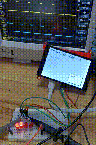
Connect 4 LEDs(with resistor, such as 100 ohm)serial connected to ESP32 3.5” display breakout pins 5/18/19/21, and download the sketch to Makerfabs ESP32 3.5” display board:
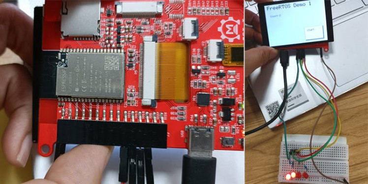
You will see the LEDs blinks, and the display counts with stop/start touch. With an oscilloscope, you can also check that the signal is neat, and in-time;
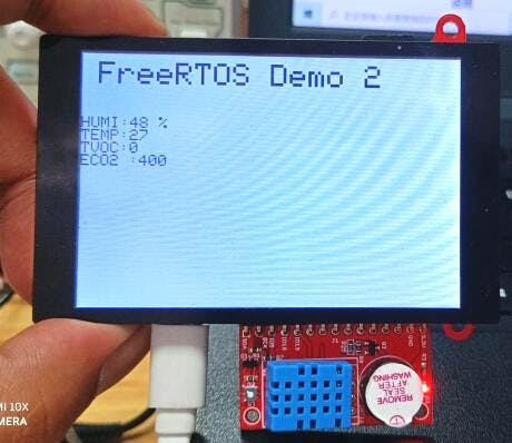
FreeRTOS Demo_2
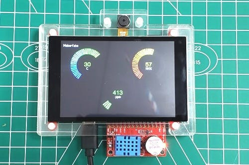
Makerfabs Indoor Environment Expansion is dedicated to CO2/TVOC/Temperature monitoring, It can be directly plugged into the ESP32 3.5” display breakout pins.
Same the Demo_1, in setup(), there we created 4 tasks:
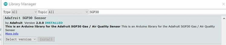
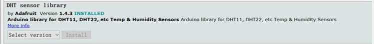
*The Adafruit SGP30 library and DHT sensor library should be installed in advance*
void setup()
{
    Serial.begin(115200);

    pinMode(LCD_CS, OUTPUT);

    SPI.begin(SPI_SCK, SPI_MISO, SPI_MOSI);
    Wire.begin(I2C_SDA, I2C_SCL);

    xTaskCreatePinnedToCore(Task_TFT, "Task_TFT", 4096, NULL, 3, NULL, ARDUINO_RUNNING_CORE);
    xTaskCreatePinnedToCore(Task_DHT11, "Task_DHT11", 2048, NULL, 2, NULL, ARDUINO_RUNNING_CORE);
    xTaskCreatePinnedToCore(Task_SGP30, "Task_SGP30", 2048, NULL, 1, NULL, ARDUINO_RUNNING_CORE);
    xTaskCreatePinnedToCore(Task_BUZZ, "Task_BUZZ", 2048, NULL, 1, NULL, ARDUINO_RUNNING_CORE);
}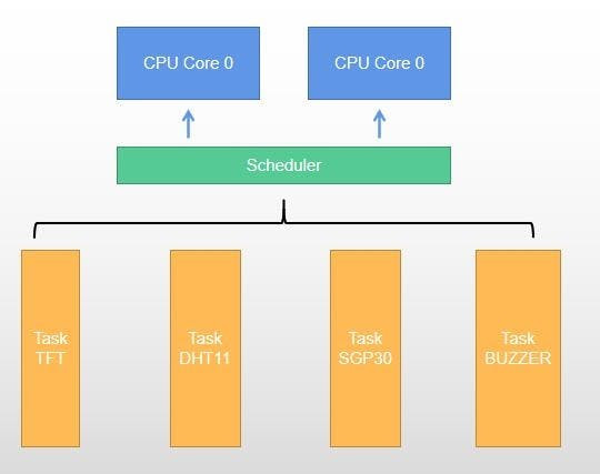
4 global values defined:
int humidity_value = 0;
int temperature_value = 0;
int tvoc_value = 0;
int co2_value = 0;
And then Task_TFT/ Task_DHT11/ Task_SGP30/ Task_BUZZ initiated.
…
xTaskCreatePinnedToCore(Task_SGP30, "Task_SGP30", 2048, NULL, 1, NULL, ARDUINO_RUNNING_CORE);…
…
In the task definition, there the SGP30/DHT11 communicate with ESP32, and the result was calculated, and then set to globe parameter, for display. And the buzz is controlled separately:
…
xTaskCreatePinnedToCore(Task_SGP30, "Task_SGP30", 2048, NULL, 1, NULL, ARDUINO_RUNNING_CORE);…
…
In the task definition, there the SGP30/DHT11 communicate with ESP32,  and result was calculated, and then set to globe parameter, for displaying. And the buzz is controlled separately:
void Task_SGP30(void *pvParameters)
{
    (void)pvParameters;

    if (!sgp.begin())
    {
        while (1)
        {
            Serial.println("SGP30 not found.");
            vTaskDelay(5000);
        }
    }

    while (1)
    {
        int humidity = humidity_value;
        int temperature = temperature_value;

        sgp.setHumidity(getAbsoluteHumidity(temperature, humidity));

        if (!sgp.IAQmeasure())
        {
            Serial.println("Measurement failed");
            continue;
        }
        Serial.print("TVOC ");
        Serial.print(tvoc_value = sgp.TVOC);
        Serial.print(" ppbt");
        Serial.print("eCO2 ");
        Serial.print(co2_value = sgp.eCO2);
        Serial.println(" ppm");

        vTaskDelay(500);
    }
}
The full code is available at: https://github.com/Makerfabs/ESP32-RTOS
With FreeRTOC, the Arduino logic gets more clear& neat, especially when the projects get complex. Of course, the Multi-task is only the first step of FreeRTOS, there are many other specs such as mailbox/ ring buffer, that would make the ESP32 easier for programming with Arduino IDE. A good place to learn more at here.
If you have further questions about implementing FreeRTOS with Arduino IDE On ESP32 TFT Display, or need some Turnkey PCBA Solutions, please contact service@makerfabs.com.
Credits
Makerfabs01
Makerfabs, Turnkey PCB Assemblies | Small Batch PCBA Prototyping | IoT Hardware Engineering.
Related products


Leave your feedback...