
How To Use An Oled Display With Raspberry Pi Pico

Made by rau7han / Displays / Photos & Video / Retro Tech / IoT
About the project
N this tutorial we will learn about the Interfacing of SSD1306 OLED Display with Raspberry Pi Pico.
Project info
Items used in this project
Hardware components

Story
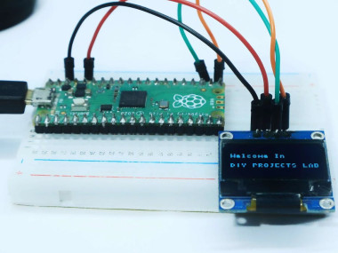
SSD1306 Oled display with Raspberry pi pico - In a majority of the projects, we need display units for printing text and sensor values. Nowadays, one of the most commonly used displays is the Oled display.
The one you can see on the screen is the SSD1306 I2C-supported Oled display Module which I am going to use with Raspberry Pi Pico.
Thank You NextPCB:
This project is successfully completed because of the help and support from NextPCB. Guys if you have a PCB project, please visit their website and get exciting discounts and coupons.
- Only 0$ for 5-10pcs PCB Prototypes:Nextpcb.com/pcbprototype
- 4-layer PCB price reduction up to 40%: Nextpcb.com/4-layer-PCB
- Register and get $100 from NextPCB: Nextpcb.com/coupon
Why NextPCB
- Most Efficient, Economic, Innovative PCB Solutions
- Higher Quality
- Lower Cost
- Faster Delivery
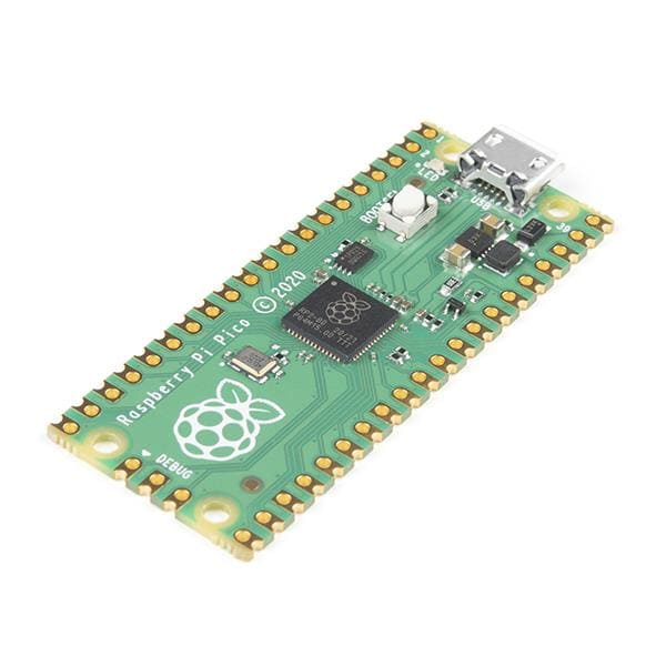
Getting Started Raspberry Pi Pico – Pinout, Specs – Beginner Guide
Hardware Required- 4pins 0.96" 128×64 OLED Display Module
- Raspberry Pi Pico
- Breadboard
- Connecting Wires
diyprojectslab.com

diyprojectslab.com
The 0.96" 128x64 OLED display module is a compact, low-cost display module that is perfect for any project that requires a small display screen.
The module is very easy to use, with only four pins required to interface with a microcontroller. The display is clear and bright, and the module is extremely thin, making it ideal for use in portable applications.
OLED Display FeaturesOLED (organic light-emitting diode) displays are low-power consumption output devices able to show text and images by controlling every single pixel.
The most common size is 128×64 pixels (0.96 inches), but also the 128×32 pixels (0.91 inches) is available from e-shops.
Their screens are usually mono-colour or bi-colour. The mono-colour ones are made of blue or white pixels, while the bi-colour models usually have an upper part yellow and the lower one blue.
In this tutorial, I’m going to use the bi-colour model, but this uses also the mono-colour ones.
Circuit Diagram - SSD1306 OLED Display with Raspberry Pi Picodiyprojectslab.com

diyprojectslab.com
You can guide to the circuit connection of the Raspberry Pi Pico and OLED display module as shown below.
- The SDA pin of the OLED Display Module is connected to the GPIO16(Pin21)
- The SCL pin is connected to the GPIO17(Pin22).
- The Vcc pin is connected to the 3.3v Pin of the Pico Board which is Pin36.
- The Ground pin of the Display module is connected to the Ground pin of the Pico board which is Pin38
I prefer Thonny IDE for programming. The programming here is divided into two main parts:1. SSD1306.py2. Main.py
MicroPython SSD1306 I2C Library
This is because the OLED Display requires an SSD1306 Driver Code first. We have to write the code for the SSD1306 Driver first. After uploading the SSD1306 Code, we can then run the main.py code.
ssd1306.py
# MicroPython SSD1306 OLED driver, I2C and SPI interfaces

from micropython import const
import framebuf


# register definitions
SET_CONTRAST = const(0x81)
SET_ENTIRE_ON = const(0xA4)
SET_NORM_INV = const(0xA6)
SET_DISP = const(0xAE)
SET_MEM_ADDR = const(0x20)
SET_COL_ADDR = const(0x21)
SET_PAGE_ADDR = const(0x22)
SET_DISP_START_LINE = const(0x40)
SET_SEG_REMAP = const(0xA0)
SET_MUX_RATIO = const(0xA8)
SET_COM_OUT_DIR = const(0xC0)
SET_DISP_OFFSET = const(0xD3)
SET_COM_PIN_CFG = const(0xDA)
SET_DISP_CLK_DIV = const(0xD5)
SET_PRECHARGE = const(0xD9)
SET_VCOM_DESEL = const(0xDB)
SET_CHARGE_PUMP = const(0x8D)

# Subclassing FrameBuffer provides support for graphics primitives
# http://docs.micropython.org/en/latest/pyboard/library/framebuf.html
class SSD1306(framebuf.FrameBuffer):
    def __init__(self, width, height, external_vcc):
        self.width = width
        self.height = height
        self.external_vcc = external_vcc
        self.pages = self.height // 8
        self.buffer = bytearray(self.pages * self.width)
        super().__init__(self.buffer, self.width, self.height, framebuf.MONO_VLSB)
        self.init_display()

    def init_display(self):
        for cmd in (
            SET_DISP | 0x00,  # off
            # address setting
            SET_MEM_ADDR,
            0x00,  # horizontal
            # resolution and layout
            SET_DISP_START_LINE | 0x00,
            SET_SEG_REMAP | 0x01,  # column addr 127 mapped to SEG0
            SET_MUX_RATIO,
            self.height - 1,
            SET_COM_OUT_DIR | 0x08,  # scan from COM[N] to COM0
            SET_DISP_OFFSET,
            0x00,
            SET_COM_PIN_CFG,
            0x02 if self.width > 2 * self.height else 0x12,
            # timing and driving scheme
            SET_DISP_CLK_DIV,
            0x80,
            SET_PRECHARGE,
            0x22 if self.external_vcc else 0xF1,
            SET_VCOM_DESEL,
            0x30,  # 0.83*Vcc
            # display
            SET_CONTRAST,
            0xFF,  # maximum
            SET_ENTIRE_ON,  # output follows RAM contents
            SET_NORM_INV,  # not inverted
            # charge pump
            SET_CHARGE_PUMP,
            0x10 if self.external_vcc else 0x14,
            SET_DISP | 0x01,
        ):  # on
            self.write_cmd(cmd)
        self.fill(0)
        self.show()

    def poweroff(self):
        self.write_cmd(SET_DISP | 0x00)

    def poweron(self):
        self.write_cmd(SET_DISP | 0x01)

    def contrast(self, contrast):
        self.write_cmd(SET_CONTRAST)
        self.write_cmd(contrast)

    def invert(self, invert):
        self.write_cmd(SET_NORM_INV | (invert & 1))

    def show(self):
        x0 = 0
        x1 = self.width - 1
        if self.width == 64:
            # displays with width of 64 pixels are shifted by 32
            x0 += 32
            x1 += 32
        self.write_cmd(SET_COL_ADDR)
        self.write_cmd(x0)
        self.write_cmd(x1)
        self.write_cmd(SET_PAGE_ADDR)
        self.write_cmd(0)
        self.write_cmd(self.pages - 1)
        self.write_data(self.buffer)


class SSD1306_I2C(SSD1306):
    def __init__(self, width, height, i2c, addr=0x3C, external_vcc=False):
        self.i2c = i2c
        self.addr = addr
        self.temp = bytearray(2)
        self.write_list = [b"x40", None]  # Co=0, D/C#=1
        super().__init__(width, height, external_vcc)

    def write_cmd(self, cmd):
        self.temp[0] = 0x80  # Co=1, D/C#=0
        self.temp[1] = cmd
        self.i2c.writeto(self.addr, self.temp)

    def write_data(self, buf):
        self.write_list[1] = buf
        self.i2c.writevto(self.addr, self.write_list)


class SSD1306_SPI(SSD1306):
    def __init__(self, width, height, spi, dc, res, cs, external_vcc=False):
        self.rate = 10 * 1024 * 1024
        dc.init(dc.OUT, value=0)
        res.init(res.OUT, value=0)
        cs.init(cs.OUT, value=1)
        self.spi = spi
        self.dc = dc
        self.res = res
        self.cs = cs
        import time

        self.res(1)
        time.sleep_ms(1)
        self.res(0)
        time.sleep_ms(10)
        self.res(1)
        super().__init__(width, height, external_vcc)

    def write_cmd(self, cmd):
        self.spi.init(baudrate=self.rate, polarity=0, phase=0)
        self.cs(1)
        self.dc(0)
        self.cs(0)
        self.spi.write(bytearray([cmd]))
        self.cs(1)

    def write_data(self, buf):
        self.spi.init(baudrate=self.rate, polarity=0, phase=0)
        self.cs(1)
        self.dc(1)
        self.cs(0)
        self.spi.write(buf)
        self.cs(1)
Now hit the download & run button. So you will be able to see the SSD1306 driver saved in the Raspberry Pi Pico.
main.pyOpen a new tab again in the ThonnyIDE. Copy the following code and paste it on the Thonny IDE Window. Save the file by the name main.py.
from machine import Pin, I2C
from ssd1306 import SSD1306_I2C
WIDTH =128
HEIGHT= 64
i2c=I2C(0,scl=Pin(1),sda=Pin(0),freq=200000)
oled = SSD1306_I2C(WIDTH,HEIGHT,i2c)
while True:
    oled.fill(0)
    oled.text("DIY PROJECTS LAB", 0, 0)
    oled.text("Tutorial", 0, 40)
    oled.show()
You need to select the Raspberry Pi Pico and then name the file as “ssd1306.py” and click on save. Then do the same process for the “main.py” file. This method allows you to run the program when the Pico will be powered up.
Thonny IDE

Thonny IDE
Working demo of the OLED Display Raspberry Pi PicoYou can refer to the following video to interface an OLED with the Raspberry Pi Pico board.
I hope you have managed to get this working and enjoy the result. You now have a tested starting point for your own projects.
Questions and comments welcome
Read Similar Articles:- Getting Started Raspberry Pi Pico – Pinout, Specs – Beginner Guide
- HC-SR04 Ultrasonic Distance Sensor With Raspberry Pi Pico Tutorial
- Interfacing PIR Motion Sensor with Raspberry Pi Pico
- Raspberry Pi Pico Home Automation System
- Interface Servo Motor With Raspberry Pi Pico
- Interface 0.96″ OLED Display with Raspberry Pi Pico
- Raspberry Pi Pico Weather Station Using Dht11 Sensor
- Interface 16*2 LCD Display With Raspberry Pi Pico
Schematics, diagrams and documents
Code
Credits
Related products


Leave your feedback...