

Items used in this project
Hardware components

Software apps and online services
Story
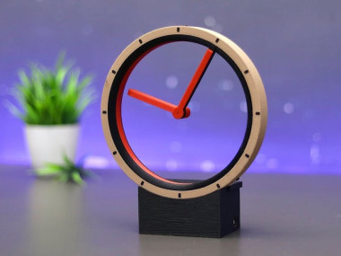
Hey Guys, in this video I will show you how I made this amazing hollow clock using Arduino in a very easy way.
Before starting let me tell you some basic information about hollow clocks,
The Arduino Hollow Clock is a unique project that combines art and technology to create a mesmerizing and functional timepiece. This clock features a minimalist design, with a hollowed-out frame that reveals the inner workings of the clock.
In this article, we'll look closer at the Arduino Hollow Clock, how it works, and how you can build one for yourself.
Thank You NextPCB:
This project is successfully finished because of the help and sponsorship from NextPCB. Guys if you have a PCB project, please visit their website and get exciting discounts and coupons, and more.
- Only 0$ for 5-10pcs PCB Prototypes:Nextpcb.com/pcbprototype
- Register and get $100 from NextPCB: Nextpcb.com/coupon
Why NextPCB
- Most Efficient, Economic, Inventive PCB Solutions
- Higher Quality
- Lower Price
- Faster Delivery
What is the Arduino Hollow Clock?
The Arduino Hollow Clock is a clock that is built using an Arduino board, 3D-printed parts, a stepper motor, and some other electronic components. The clock is designed to be placed on a desk, and it features a hollowed-out frame that allows you to see the inner workings of the clock.
The clock is powered by a USB power supply, and it is programmed to display the time using a series of geared movements mounted on the inside of the frame. The Frame is arranged in a circular pattern, and they keep moving to indicate the current time.
The Arduino Hollow Clock is a unique and fascinating project that combines art and technology to create a functional and beautiful timepiece. Whether you're an electronics enthusiast, an artist or just someone who loves cool gadgets, building an Arduino Hollow Clock is a fun and rewarding project that you're sure to enjoy.
The main source of this project is from the project Shinsaku Hiura , I will give full credit to the authors of this project.
SuppliesIf you want to build your own Arduino Hollow Clock, you'll need a few things. Here's what you'll need:
- An Arduino board ( Amazon /AliEexpress)
- Stepper motor and driver board ( Amazon /AliEexpress)
- Neodymium Magnets ( Amazon /AliEexpress)
- A power source (such as a 9V battery or USB) ( Amazon /AliEexpress)
- A hollowed-out frame or box(which we will be 3d printing) ( Amazon /AliEexpress)
- Arduino IDE and Programming Cable
- PCB(Optional)
Tools Used:
Soldering Iron ( Amazon /AliEexpress)
3D printer ( Amazon /AliEexpress)
Wire Cutter
Wire Stripper
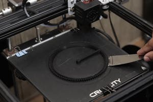
3D Printing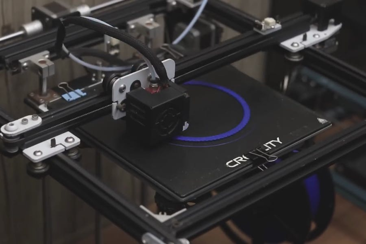
3D printing parts using a 3d printer is a fun job! I have listed all the parts that we will be using to build this project
You can use your own 3d printer to get the parts, just download the STL file from below and slice them using any slicing software, in my case, I am using Cura.
After slicing you can upload the files to 3d printer via a memory card and finally start printing.
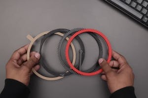
The choice of filaments is left up to you, I recommend using the colors that I printed because it matches to any theme color of your desktop!
Arduino Circuit Diagram and CodesOnce you have all of the necessary components, you'll need to wire everything together according to the schematic for the clock. You can find a schematic above.
The circuit diagram is straightforward.
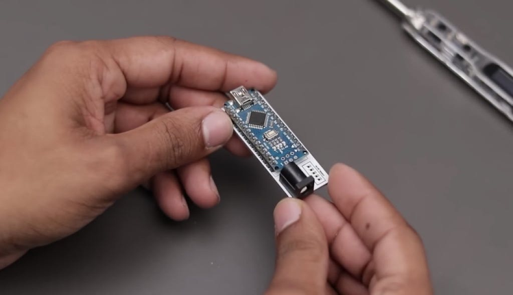
All you need to do is connect the stepper motor driver to the Arduino Uno board first, later we can connect stepper motor wires to the driver
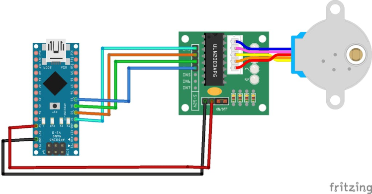
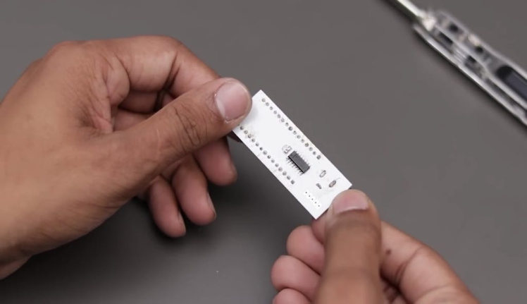
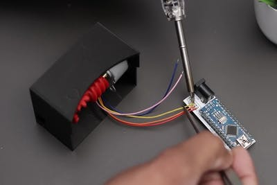
As we want to make this gadget as small as possible we will be trimming the extra wires from the stepper motors and later solder the wires directly to the board
I have used a custom PCB to reduce the use of wires, if you don't have PCB you can make a direct connection with wires too
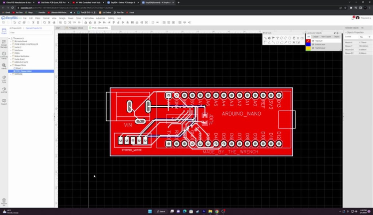
- Only 0$ for 5-10pcs PCB Prototypes:Nextpcb.com/pcbprototype
- Register and get $100 from NextPCB: Nextpcb.com/coupon
Once you have the circuit ready you can upload the codes, by directly copying and pasting the below Arduino codes I your IDE and clicking on upload.
Assembling 3d Printed Parts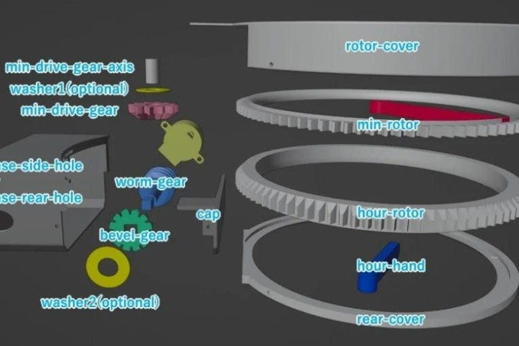
It is not rocket science to assemble the 3d printed parts!
I have provided the map that shows how to assemble the parts in the first image of this step.
That will be the tool that simplifies the assembly process, it took me around 10 minutes with all the supplies ready to assemble the top part.
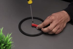
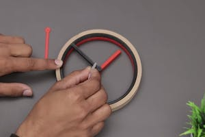
We will first start to assemble the inner dials of the clock.
The black ring that moves has a small extension to which we will be pasting the dial stick.
Just place a drop of glue and keep it on the top of the dial and we are good to go
Step 4: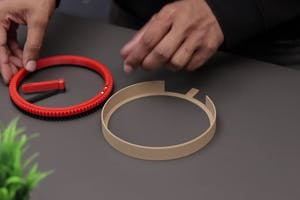

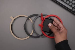
Neodymium magnets help the hollow parts that carry the dial to work effectively.
As you can see in the above step images the red geared circle carries a place to hold the neodymium magnets.
Just insert the magnets and add drops of super glue, Later this frame will be placed on top of another ring
If you feel any difficulties in following up these steps you can always watch the tutorial given at the end of this instructable.
Preparing Base

This is the most important part of this project as it drives the hollow clock dials.
The 3d printed box along with a few gears is assembled in a place provided inside the box.
Refer to the images above on these steps that show a simple way to put all this together without any effort
Later we will adding electronics inside this box so make sure the gears are properly fit and wont come out when they are working.
Installing Electronics

This is a very easy step, don't panic!
We have already prepared the electronics, all we need to do is just put them together.
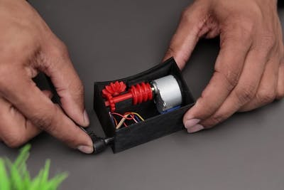
Start by adding a stepper motor to the base box to which we added gears before.
Solder the wires directly to the Arduino board.
Insert all the electronics into the dedicated slot given inside the base box, and make sure to keep the power pin easily accessible outside the box before covering the top lid.
Setting Up to Work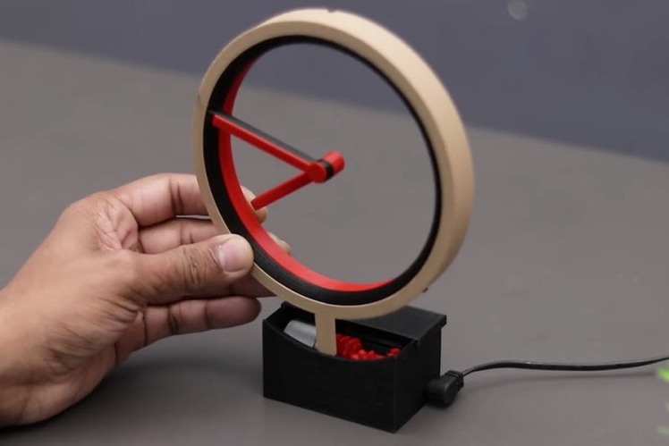

Once we have the base ready and installed with mechanisms we can just add the top frame.
This top frame or what we can call clock dials has some gears within, This will be connected with the base worm gears.
As soon you connect the base to the USB power supply(via Arduino cable) The gears start to move.
Initially, you might need to adjust the time, Once the time is set you can use this clock
To Show you guys that this clock works just like a real clock I have placed a clock side to side.
Video TutorialDon't miss watching this amazing video that shows the working and building of this amazing project
If you have any questions about this project you can reach out to me in the comments box.
Leave your feedback...