
Home Monitoring With Wireless Sensor Nodes

Made by electrouser880 / Home Automation
About the project
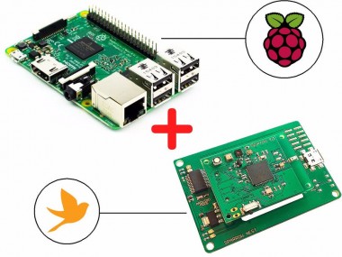
Monitor your home using this powerful tutorial. Only two components needed: a Raspberry Pi and a Sparrow Sensor Node Kit.
Project info
Difficulty: Moderate
Platforms: DeviceHub.net, Raspberry Pi
Estimated time: 1 hour
License: GNU General Public License, version 3 or later (GPL3+)
Items used in this project
Hardware components


Story
Do you want to build an IoT-enabled home monitoring system that can measure environmental parameters and also detect intrusion but don't know where to start? This easy tutorial will deliver everything you need with only two major components: a Raspberry Pi and a Sparrow Wireless Sensor Node kit. No soldering, and minimal wiring needed!
With this system, you will be able to remotely monitor and log temperature, humidity, pressure, luminosity, IR and UV indexes and also detect intrusion. The system is also extensible, you will be able to add multiple wireless sensors to your home, monitoring every room in your house or outdoor parameters.
For this project you will need a Raspberry Pi, two Sparrow Wireless Sensor Nodes and two Sparrow Nest programming boards. Also, if you want intrusion detection to work, you will need a PIR sensor.
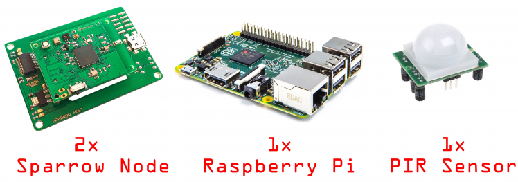 Hardware modules you'll need for this build. The PIR sensor is optional.
Sparrow Nodes
First, you will need to install the Arduino IDE and also the patch to make it work with the Sparrow nodes. You will find everything you need in this tutorial.
Each Sparrow node has integrated sensors for temperature, pressure, humidity and light levels, so we will need to write a small program that periodically reads these values and sends them through the serial port. While it's not mandatory, it would be a good idea to check out the basic tutorials here in order to get accustomed to the sensor node.
For this project, you will need to install the following libraries for the Arduino IDE: SHT2x for the temperature/humidity sensor, Adafruit's Si1145 for the light sensor and MS5637 for the barometer/altimeter.
We will also be using the SparrowTransfer library for the wireless transmission of >here.
The project configuration will be the following:
- A remote sensor node with the PIR attached to it, sending presence data.
- A receiver node, measuring also environmental parameters (temperature, humidity, light etc.) connected to the Raspberry Pi.
-
Raspberry Pi connected to the Internet and sending all sensor data to
DeviceHub.
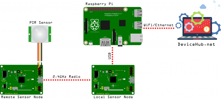 Project Diagram
The Remote Sparrow Node
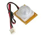
Connect your Sparrow node to your computer through its Sparrow Nest adapter. Also, if you have the PIR sensor, connect it to the board like this:
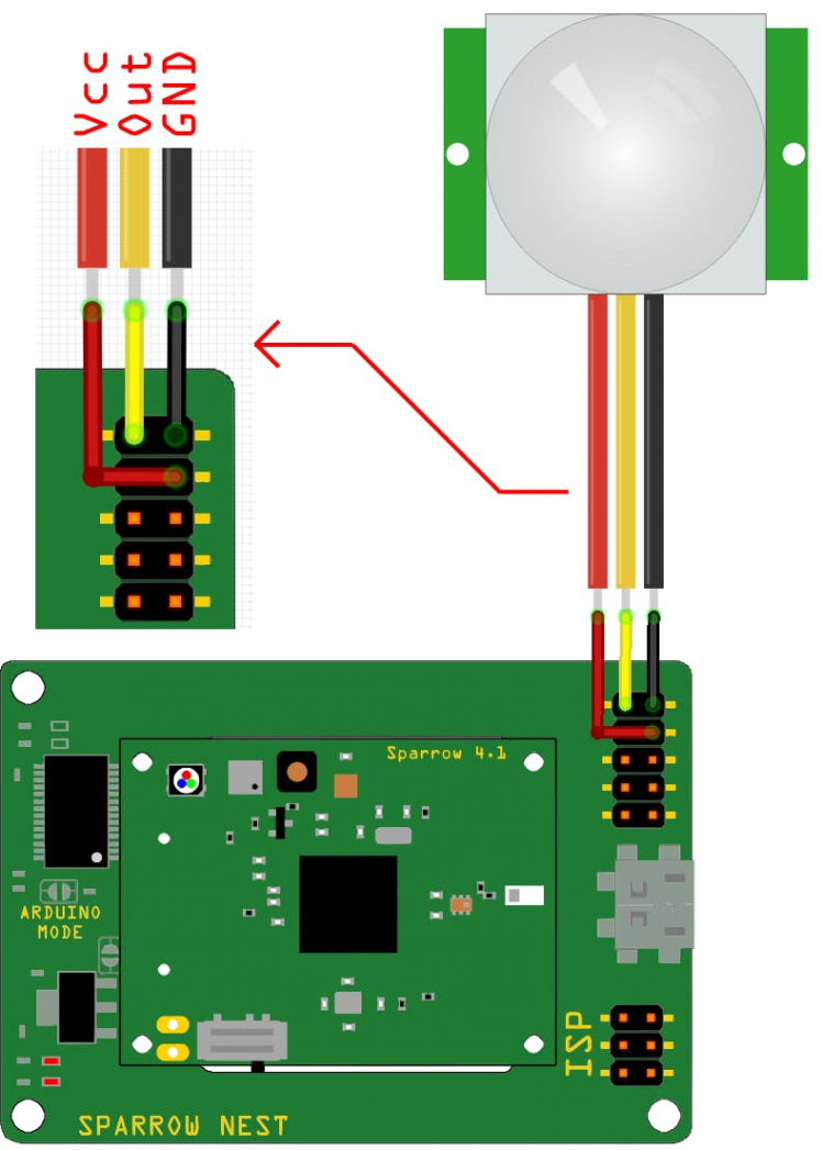 PIR sensor connection diagram
Now, let's write a simple program on the Sparrow node that will read the PIR state, the temperature and then send them through the radio transceiver:
#include "SparrowTransfer.h"
#include <Wire.h>
#include <SHT2x.h>
#define DEBUG 1
//create object
SparrowTransfer ST;
struct SEND_DATA_STRUCTURE{
 //put your variable definitions here for the data you want to send
 //THIS MUST BE EXACTLY THE SAME ON THE OTHER SPARROW
 uint8_t presence;
 float temperature;
};
//give a name to the group of data
SEND_DATA_STRUCTURE mydata;
int redLedPin = 8;              // red LED
int greenLedPin = 11;           // green LED
int inputPin = 18;              // choose the input pin (for PIR sensor)
int pirState = LOW;             // we start, assuming no motion detected
int controlPin = 7;             // sensor on/off control
uint8_t detect(){
 int val = digitalRead(inputPin);  // read PIR input value
 if (val == HIGH) {            // check if the input is HIGH
     digitalWrite(redLedPin, LOW);  // turn LED ON
     return 1;
   }
 else {
     digitalWrite(redLedPin, HIGH); // turn LED OFF
     return 0;
   }
}
void blinkLED() //blinks the green LED
{
 digitalWrite(greenLedPin,LOW);
 delay(20);
 digitalWrite(greenLedPin,HIGH);
}
void setup(){
 pinMode(greenLedPin, OUTPUT);      // declare green LED as output
 pinMode(redLedPin, OUTPUT);        // declare red LED as output
 pinMode(inputPin, INPUT);          // declare sensor as input
 pinMode(controlPin, OUTPUT);       // declare sensor control pin as output
 digitalWrite(controlPin, LOW);     // turn on sensors
 delay(1000);
 Wire.begin();
 //start the library, pass in the data details
 ST.begin(details(mydata));
 mydata.presence = 0;
 mydata.temperature = -1.23; //default value to test if something is wrong
 digitalWrite(greenLedPin, HIGH); //start with all LEDs off
 digitalWrite(redLedPin, HIGH);
 #ifdef DEBUG //only for local debugging purposes
   Serial.begin(9600);
 #endif
}
void loop(){
 mydata.presence = detect();
 mydata.temperature = SHT2x.GetTemperature();
 #ifdef DEBUG
   Serial.println(mydata.presence);
   Serial.println(mydata.temperature);
 #endif
 ST.sendData();
 blinkLED();
 delay(1000);
}
When opening the Serial Monitor from the Arduino IDE, you should see data coming in from the PIR and temperature sensors. Check if the data is correct, and then reprogram the node with #define DEBUG 0.
The Local Sparrow Node
Connect your second Sparrow node to your computer through its Sparrow Nest adapter. We will write a program that reads sensor values about every ten seconds and outputs them on the serial port in CSV format:
#include <Wire.h>
#include "SI1145.h"
#include <SHT2x.h>
#include <BaroSensor.h>
#include "SparrowTransfer.h"
//create object
SparrowTransfer ST;
struct RECEIVE_DATA_STRUCTURE{
 //put your variable definitions here for the data you want to receive
 //THIS MUST BE EXACTLY THE SAME ON THE OTHER ARDUINO
 uint8_t presence;
 float temperature;
};
//give a name to the group of data
RECEIVE_DATA_STRUCTURE mydata;
struct SENSOR_DATA{
 //we store here sensor readings
 float temperature;
 float humidity;
 float pressure;
 float light;
 float IR;
 float UV;
 uint8_t remote_presence;
 float remote_temp;
};
SENSOR_DATA node;
int controlPin = 7; // control pin for all sensors on the node
int greenLedPin = 11; // green LED
Adafruit_SI1145 uv = Adafruit_SI1145();
int getSensorData(){ //reads all sensors
 node.temperature = SHT2x.GetTemperature(); //temperature in degrees C
 node.humidity = SHT2x.GetHumidity(); //humidity in RH
 node.pressure = BaroSensor.getPressure(); //pressure in mbar
 node.light = uv.readVisible(); //visible light
 node.IR = uv.readIR(); //infrared light level
 node.UV = uv.readUV() / 100.0; //UV index
 return 1;
}
void blinkLED() //blinks the green LED
{
 digitalWrite(greenLedPin,LOW);
 delay(20);
 digitalWrite(greenLedPin,HIGH);
}
void sendSensorData(){ //sends sensor data over the serial interface as CSV
 Serial.print(node.temperature); //temperature in degrees C
 Serial.print(",");
 Serial.print(node.humidity); //humidity in RH
 Serial.print(",");
 Serial.print(node.pressure); //pressure in mbar
 Serial.print(",");
 Serial.print(node.light); //visible light
 Serial.print(",");
 Serial.print(node.IR); //infrared light level
 Serial.print(",");
 Serial.print(node.UV); //UV index
 Serial.print(",");
 Serial.print(node.remote_presence); // presence from the remote sensor
 Serial.print(",");
 Serial.println(node.remote_temp); // temperature from the remote sensor
}
void uvInit(){ // initializes the Si1145 light sensor
 if (! uv.begin()) { //no luck first time, try to initialize again
   Serial.println("Didn't find Si1145");
   digitalWrite(controlPin, HIGH);
   delay(100);
   digitalWrite(controlPin, LOW);
   delay(1000);
   if (! uv.begin()) while(1); //the light sensor could not be initialized
 }
}
void setup() {
 //start the library, pass in the data details
 ST.begin(details(mydata));
 pinMode(controlPin, OUTPUT);  //sensor on/off control
 pinMode(greenLedPin, OUTPUT);      // this is where the red LED on the node is connected
 digitalWrite(controlPin, LOW); // enable all sensors
 delay(1000); //wait for things to settle
 Serial.begin(9600);
 uvInit(); // init light sensor
 BaroSensor.begin(); // init barometric sensor
}
void loop() {
 if(ST.receiveData()){ //check remote sensor readings
   node.remote_presence = mydata.presence;
   node.remote_temp = mydata.temperature;
 }
 if(getSensorData()){
   sendSensorData();
   blinkLED();
 }
 delay(1000);
}
Open the Serial Monitor window to check sensor output is available and consistent.
First three values should be light levels, in the visible, infrared and UV spectrum, followed by temperature, humidity and barometric pressure. We also the presence and temperature values from the remote sensor.
Check if they are consistent and that they have no errors. If they don't update, the remote sensor node is not in range, and you will need to bring it closer. Usually, inside a house this means a radius of about 15m from the receiving node.
Connecting the Raspberry Pi
The next step after programming the Sparrow node is to connect your Raspberry Pi to your local network and write a small Python script to parse the CSV stream from the sensor node.
Connect your Sparrow node to one of the USB ports of your Raspberry Pi and check if it mounted properly. It should appear as a ttyUSBx port in /dev.
pi@raspberrypi:~ $ lsusb
Bus 001 Device 004: ID 0403:6001 Future Technology Devices International, Ltd FT232 USB-Serial (UART) IC
pi@raspberrypi:~ $ ls /dev/ttyUSB*
/dev/ttyUSB0
First, let's write a small Python program to read what the sensor node outputs on the serial line:
from time import sleep
import serial
# Make sure you have the correct port and baud rate selected
ser=serial.Serial('/dev/ttyUSB0', 9600)
while True:
       line = ser.readline()
       print line
       sleep(1.0)
Next, we run it and, if everything is in order, we should be getting something like this as an output:
pi@raspberrypi:~ $ python myserial.py
28.24,27.21,998.84,279.00,403.00,0.12,0,28.52
28.24,27.19,998.80,280.00,403.00,0.12,0,28.54
28.21,27.18,998.86,278.00,402.00,0.11,0,28.50
28.19,27.19,998.82,279.00,404.00,0.12,0,28.52
DeviceHub
To access sensor >DeviceHub for this task, as it provides an easy way to send data, view sensor logs and also send commands back to the RaspberryPi.
To gain access, you will first need to create an account. After registering, select Project>New Project and give your project a name. After creation, your project will gain a Project ID and an API Key, which will identify it on the platform.
Now, you must add a new device to your project, so select Add Device and name it as you wish. Select RaspberryPi as Device Type, Python for Programming Language and Ethernet or WiFi as Connection Type. The device will also be assigned an unique Device UUID.
Each device can have multiple sensors and actuator which can be easily added through the web interface, so let's create six sensors to correspond to our device sensors. Name them Temperature, Humidity, Pressure, Light, IR, and UV. Let's also add the two sensors from the remote Sparrow node. Name them Remote_Presence an Remote_Temperature. Each time you add a sensor, you must select its data type and (optionally) measurement unit. All sensors output analog data, so select Analog for each.
At the end, your dashboard should look similar to this:
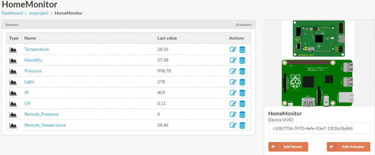 DeviceHub dashboard after adding all sensors
Sending Data to DeviceHub
We can easily send and receive data to DeviceHub through its API. Back on the Raspberry Pi, we will need to install DeviceHub libraries for Python:
pi@raspberrypi:~ $ pip install devicehub
Now, let's modify the first Python code to parse the CSV stream and send data to DeviceHub. You will need to fill in the Project ID, Device UUID and API Key data from your own project in the code below:
from devicehub import Sensor, Device, Project
from time import sleep
from random import randint
import serial
PROJECT_ID      = 'your Project ID'
DEVICE_UUID     = 'your Device UUID'
API_KEY         = 'your API Key'
SENSOR_NAMES    = ['Temperature', 'Humidity', 'Pressure', 'Light', 'IR', 'UV', 'Remote_Presence', 'Remote_Temperature']
SENSOR_VALUES   = []
SENSORS         = []
def add_sensor(type, name, dev):
       AN = Sensor(type, name)
       dev.addSensor(AN)
       return AN
def analog_input(dev, sensor, value):
       sensor.addValue(float(value))
       dev.send()
       return
ser=serial.Serial('/dev/ttyUSB0', 9600)
ser.flushInput()
ser.flushOutput()
line = ser.readline()
line = ser.readline()
print 'first', line
project = Project(PROJECT_ID, ssl_verify=False)
device = Device(project, DEVICE_UUID, API_KEY)
for s in SENSOR_NAMES:
       num = add_sensor(Sensor.ANALOG, s, device)
       SENSORS.append(num)
while True:
       try:
               SENSOR_VALUES = []
               line = ser.readline()
               print line
               print len(line)
               fields = line[:-1].split(',')
               #if( len(line) > 35 and fields != None):
               if(fields != None):
                       for f in fields:
                               SENSOR_VALUES.append(f)
                       for i in range(0, 8):
                               print SENSOR_NAMES[i], SENSOR_VALUES[i]
                               analog_input(device, SENSORS[i], SENSOR_VALUES[i])
                       print 'Data Sent OK!'
       except:
               print 'Something went wrong, retrying...'
       sleep(8.0)
If the code runs well, you should be able to see data coming into DeviceHub and the plot for each sensor advance with every new reading.
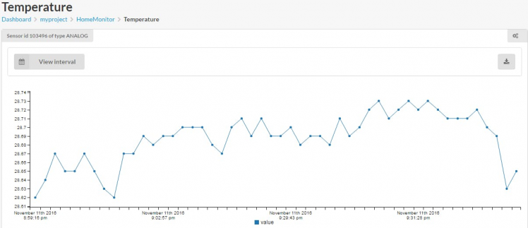 Temperature Plot
The Completed Project
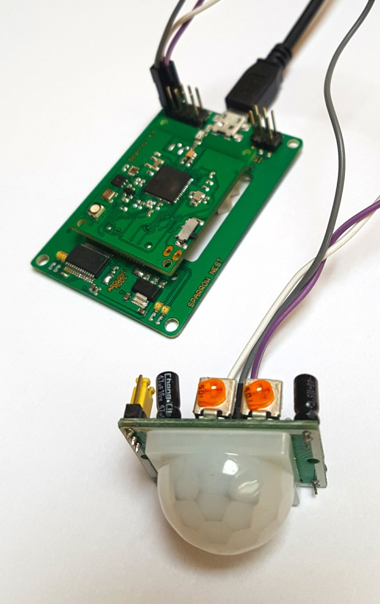
Here's some photos of my completed project. You might want to power the remote node from a separate wall USB plug, any decent smartphone charger will do. Also, you might want to enclose the node in a nice case, I haven't had the time to do that.
 Remote Wireless Sensor Node
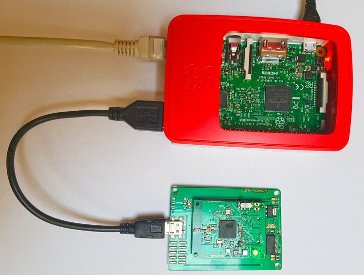 RaspberryPi and Local Node
I've uploaded the code and all files to a GitHub repo. The project can be expanded by adding even more remote sensors, monitoring the environment in as rooms and locations as you need. Happy hacking!
Leave your feedback...