
Hand Gesture Controlled Appliance Switch

Made by electrouser1509 / Home Automation
About the project
Control appliance using a hand gesture without any microcontroller, only bare electronic components.
Project info
Difficulty: Moderate
Platforms: Texas Instruments
Estimated time: 1 hour
License: GNU General Public License, version 3 or later (GPL3+)
Story
Every one of us felt an electric shock in our lifetime. It doesn't generally happen but sometimes physical contact with the switches may be lethal. But what if I say that you don't need to touch any switch to power On or Off your appliances? You just need to make a gesture from hand in front of a module to control the appliances. Today let's build a gesture-controlled switch which doesn't need any physical contact with the switch, just one has to take hand over the switch and toggle it on/off.
Further About the Project...
In this project, I will show you how to make a wireless circuit using photoresistor, LM741 Op-Amp IC and 4017 decade counter. When you take your hand over the photoresistor while the switch is off, it will turn the appliance on. For the second time, when you take your hand over the photoresistor again, it will toggle the switch and switch off the appliance. A photoresistor is the same as other resistors but the difference is that their resistance change with the change in light falling on it. This change in voltage is sensed by LM741 Op-Amp and this will in turn control 4017 IC output which is connected to the AC light through relay module. So, each time we move our hand over the LDR, the intensity of light drops and it will either switch on or off the AC load.
Things You Need
; ; 1 / 9
1 / 9
Note: Photoresistors are often sold in the market as the light dependent resistor (LDR). They all are same. I am using the one with the cell resistance @ luminescence : (5~10)k Ohm @ 10 lux. The link below will lead you to the one I am using in the project.
List of materials:
- 1 x CD4017 Decade Counter: http://bit.ly/2SB4Ljc
- 1 x LM741CN IC: http://bit.ly/2QJXmkw
- 1 x 5V Relay: http://bit.ly/2QOJhSI
- 1 x Photoresistor: http://bit.ly/2QKEx0l
- 1 x LED Matrix: http://bit.ly/2C45Omz
- 1 x 22 uF Capacitor: http://bit.ly/2Gdpkkt
- 1 x BC546 Transistor: http://bit.ly/2UwK9KO
- 1 x 10k Ohms Potentiometer: http://bit.ly/2RRafXf
- 1 x 9V Battery Snap/Clip: http://bit.ly/2QnWket
- 1 x Breadboard: http://bit.ly/2AFJkpQ
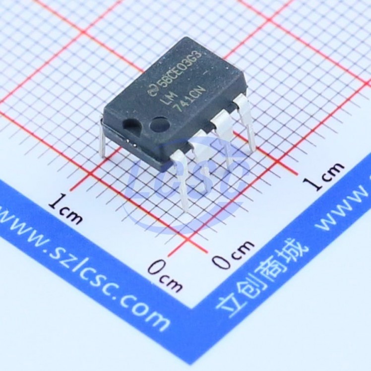
What is Op-Amp LM741?
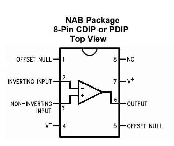 Pin diagram of LM741 Operational Amplifier
LM741 operational amplifier is a DC-coupled high gain electronic voltage amplifier. It's a small chip having 8 pins. It is used as a comparator which compares two signals. In Op-Amp IC 741, PIN2 is an inverting input terminal and PIN3 is non-inverting input terminal. The output pin of this IC is PIN6. The main function of this IC is to do the mathematical operation in various circuits.
While the voltage at non-inverting (+) is higher than the voltage at inverting input (-), then the output of the comparator is High. And if the voltage of inverting input (-) is Higher than the non-inverting end (+), then the output is LOW. In this Wireless Switch Circuit, LM741 is used to provide the Low to a high Clock pulse to IC 4017, for each time when one passes a hand over the LDR. Learn more about Op-amp 741 here.
Know More About the Decade Counter IC 4017
Pin diagram of Decade Counter IC 4017Most of us are more comfortable with 1, 2, 3, 4… rather than 001, 010, 011, 100. We mean to say that we will need a decimal coded output in many cases rather than a raw binary output. Let us now introduce you a new IC named IC 4017. It is a CMOS decade counter cum decoder circuit which can work out of the box for most of our low range counting applications. It can count from zero to ten and its outputs are decoded.
It can produce output at the 10 pins (Q0 – Q9) sequentially, means it produces output one by one at the 10 output pins. This output is controlled by a LOW to HIGH clock pulse at PIN 14 (positive edge triggering). At first, output at Q0 (PIN 3) is HIGH, then with each clock pulse, output advance to the next PIN. Like one clock pulse makes the Q0 LOW and Q1 HIGH, and then the next clock pulse makes the Q1 LOW and Q2 HIGH, and so on. After the Q9, it will start from the Q0 again. So it creates sequential ON and OFF of all the 10 OUTPUT PINs.
In this project, we have used 4017 IC to latch the output to one pin when we pass the hand over LDR. Go through CD4017 circuits to learn more about this IC. And here is one simple application of Toggle switch to understand the working of 4017 to latch the output.
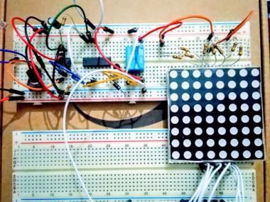
Connecting the Stuff Right
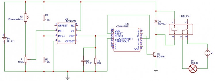
Connect the components according to the schematics shown in the image above.
Precaution: Be careful when you are connecting relay with the appliance and mains power supply. It's dangerous and you can get electrocuted. I prefer to switch off the mains supply from the main board of your house if you want to use this in your home.
I made the schematic using the EasyEDA online tool. I would recommend it because you don't need to install any software to use. It just needs a web browser and internet connection. I would recommend you to use Chrome or Firefox browser. Moreover, it is connected with lcsc.com. So, you can design schematics and PCB and order the exact product with high quality and value for money.How it works?
Initially, AC light will remain in ON condition as we have connected therelay to Q0 of 4017, and Q0 will be high by default in 4017 IC. Now, when someone firstly passes the hand over LDR as a gesture, it's resistance gets increased and according to the voltage divider rule, the voltage at PIN3 of LM417 becomes higher than PIN2, and that makes the output PIN6 of Op-Amp 741 high. The output of Op-Amp is connected to the clock PIN14 of decade counter IC 4017. As the output of Op-Amp become HIGH, it gives a LOW to a HIGH clock pulse to 4017 IC, which makes the output PIN3 (or Q0) of IC 4017 LOW and output PIN2 (or Q10) high, which turns off the light connected at Q0. Now, the light remains in OFF state until the next clock pulse, which will be generated when we again put the hand over the LDR.
The output of LM741 remains high only till we cover the light over the LDR, as soon as we remove the hand, output PIN6 of LM741 becomes low again. But, this doesn't affect the latched output of 4017 as IC 4017 only shifts its output to the next pin when it receives LOW to HIGH pulse. So, it won't be affected with HIGH to LOW pulse, generated when the output of LM741 goes HIGH to LOW.
Now when we again pass our hand over the LDR, the Op-Amp output again goes HIGH and IC 4017 again receives a Low to High clock pulse which turns the Q1 from HIGH to LOW and makes the Q2 (Pin 4) HIGH. Now here is the trick, we have fed the Q2's high output to the reset PIN15 of IC4017, which resets the IC and put the IC in default mode where Q0 will be high. So again Light will get turn on with Q0 high.
To prevent it from misbehaving or remove error in counting pulse because of bounding effect, we have used RC circuit using the capacitor of 22uf and 10k resistor at Clock PIN14 of 4017 IC, which helps it to count only one pulse on each time hand passes over the LDR.
Schematics, diagrams and documents
Credits
Related products


Leave your feedback...