
Getting Started With Psoc 6 And Modustoolbox Software

About the project
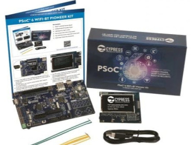
Simple project to get started PSoC 6 Wi-Fi-BT Pioneer Kit using ModusToolbox software
Project info
Difficulty: Easy
Estimated time: 1 hour
License: GNU General Public License, version 3 or later (GPL3+)
Items used in this project

Story
We are all aware of AVR,PIC,ARM, and ESPS which are widely used in embedded systems. Besides, there is one new and feature-rich IoT-enabled embedded platform, the PSoC 6 Wi-Fi-BT Pioneer Kit that has been designed for developing next-generation Internet of Things (IoT) applications. It provides developers with an ultra-low-power, flexible, and secure MCU architecture. This kit comes with a Murata Wi-Fi And Bluetooth module, which offers robust and secured Wi-Fi and Bluetooth connectivity in one chip. The Arduino UNO headers on the kit enable different types of shield interfaces to PSoC. The PSoC 6 comes with an onboard debugger/programmer (KitProg) to efficiently debug and program the target device.
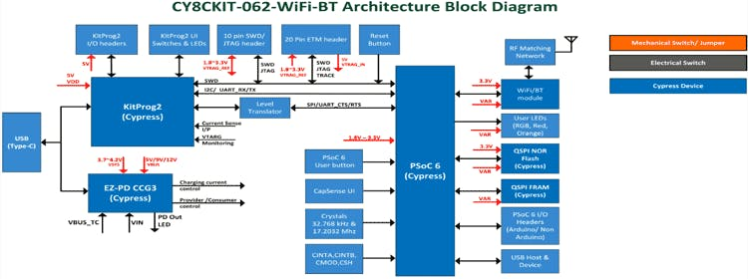
Before we go any further, let's look at the block diagram of the PSoC 6 Wi-Fi-BT Pioneer Kit to get a better understanding. The hardware diagram of the board is given below.
CY8C-KIT Architecture:
Power-Supply Sub-Section:
The total power supply section of the CY8CKIT board is shown below.

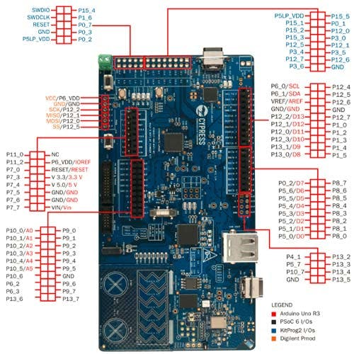
The complete pinout structure of the CY8CKITboard is shown below:
Cypress PSoC (Programmable System-on-Chip) is the world's first programmable embedded design platform that integrates discrete analog and programmable logic along with memory and a microcontroller. Easy-to-use software tools, like ModusToolbox and PSoC Creator Integrated Design Environment, simplify the design and debugging of analog front ends and digital logic while accelerating complete system designs with IoT and Bluetooth Technology. PSoC comes in four MCU options for 8-bit and 32-bit applications, ranging from the cost-optimized 8-bit M8C to the high-performance ARM Cortex-M4.
PSoC 6 WIFI BT pioneer Kit
The PSoC 6 WIFI-BT Pioneer Kit has been designed for developing next-generation Internet of Things (IoT) applications. the PSoC 6 MCU, which provides developers with an ultra-low-power, flexible, and secure MCU architecture. This kit comes with a Murata WIFI And Bluetooth module, which provides robust and secured Wi-Fi AND Bluetooth connectivity in one chip. The Arduino UNO headers on the kit, enable the different types of shield interfaces to PSoC. The PSoC6 comes with an onboard debugger/programmer (KitProg) to easily debug and program the target device.
The CY8CKIT-062-BLE features support for BLUETOOTH Low Energy (BLE) v5.0 and an onboard BLE antenna. The kit is compatible with Arduino Uno shield boards and includes a 512Mb high-speed Quad-SPI NOR flash. This kit is supported within Cypress ModusToolbox Software Environment, a set of multi-platform development tools, and a comprehensive suite of GitHub-hosted firmware libraries. Together, they enable an immersive development experience for customers creating converged MCU and Wireless systems. The PSoC 6 BLE Pioneer Kit is also now supported in the Mbed OS.
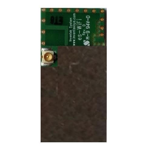
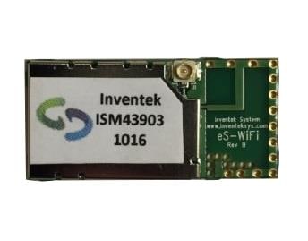
front view Of the PSoC6 Kit

front view Of the PSoC6 Kit
back view Of the PSoC6 Kit

back view Of the PSoC6 Kit
PSoC6 Microcontroller features
- The PSoC6 CY8C6247 is 32-bit dual-core MCU, with an Arm Cortex-M4 and Arm Cortex-M0 from Cypress Semiconductor.
- PSoc6 has 1MB of Flash memory, and 288KB of SRAM.
- 102 GPIO pins 7 programmable analog blocks, and 56 programmable digital blocks.
- Full-Speed USB.
- PDM-PCM digital microphone interface.
- Capacitive-sensing with Cap Sense.
- WIFI and Bluetooth radio modules, Bluetooth Low Energy with 5.0 specification.
- Cortex M4 is the Main CPU it runs at Up to 150 MHz
- Low Power 1.7-V to 3.6-V Operation gives a perfect solution for portable applications And IoT Applications.
Modus toolbox software
ModusToolbox was built to make it easier and more efficient by removing development barriers and allowing the user to create real-time applications quickly. ModusToolbox has all the features to get started with IoT easily. it has covering applications from embedded sense and control to wireless and cloud-connected systems with the easiest interfaces in less time.
ModusToolbox provides the choice of compiler, editor, debugger, and revision control system in a single standalone IDE. With ModusToolbox, you don’t have to choose between closed, proprietary flows that struggle to keep pace with modern innovations and open platforms that fail to support the unique features and value of their target device. ModusToolbox is the “best of both worlds” platform that delivers a wonderful development experience, increased productivity, and feature-rich, bullet-proof applications.
ModusToolbox was built to make your life easier and more efficient by removing development barriers and allowing you to deliver quality products to market faster.
You can download the software from the official website and can be installed. The link to download the software is herehttps://www.infineon.com/cms/en/design-support/tools/sdk/modustoolbox-software
Upgrading the Firmware of the PSoC6 Development Kit
Before Uploading any code First, we need to upgrade the firmware of the PSoC development Kit. By default, the kit comes with KitProg2 but ModusToolbox Supports firmware Kitprog3.
To update the firmware, you need to follow these steps
Step A: - Connect the USB Type C cable To KitProg 2 USB port then press and hold the SW3 and connect another end of the USB to your computer (As shown below). This Action switches the programmer to Bootloader Mode. When it enters bootloader mode LED2 on the Development kit will start blinking.
Connecting cable to KitProg2 USB

Connecting cable to KitProg2 USB
Step B: - Now open the fw-loader folder using the command prompt of your computer.
Type The fw-loader folder location and add fw-loader --update-kp3and press enter.
Firmware Upgrading status

Firmware Upgrading status
When Upgrading to New Firmware completes upgraded kitprog3 info will pop up on the computer screen (as shown above).
Creating Example Program using PSoC6 Development Kit and ModusToolbox Software: Blinking LED
Step 1: - To create a project, Open the ModusToolbox Software and give a name to the project workspace. here I have given the project workspace name LED_BLINK (as shown below). After Entering the name on the workspace click Launch.
Creating Project workspace

Creating Project workspace
Step 2: - Next Select a New application from the start menu(as shown below).
New application window

New application window
Step 3: - A project creator window will appear on the screen. here we have to Choose the Board Support Package (BSP). Under PSoC 6 BSP select CY8CKIT-062-WIFI-BT and click Next as shown.
Board supporting package selecting window

Board supporting package selecting window
Step 4: - Choose the Appropriate Application Template (For This project I am using the Empty PSoC App) and click create. it will take up to a minute to complete the Whole Process.
.Application Selection window

.Application Selection window
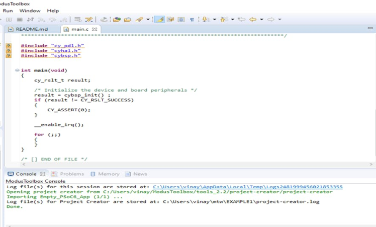
After Successful Initialization main window will appear with README.md
Main window with a readme. md

Main window with a readme. md
Step 5: - Open the main.c From Project Window as shown.
selecting main.c

selecting main.c
As soon as you click on main.c A new window will open with some lines of code already written into it.
Step 6: - Now write the code to the main.c
On the PSoc6 Kit, there are Three User LED Available, here I am utilizing User LED5 to blink.
#include "cy_pdl.h"
#include "cyhal.h"
#include "cybsp.h"
intmain(void)
{
cy_rslt_t result;
result = cybsp_init() ; /* Initialize the device and board peripherals */
CY_ASSERT(result == CY_RSLT_SUCCESS);
enable_irq();
cyhal_gpio_init(CYBSP_USER_LED5,CYHAL_GPIO_DIR_OUTPUT,CYHAL_GPIO_DRIVE_STRONG, CYBSP_LED_STATE_OFF); /* Enable LED5 As User LED Output */
for (;;)
{
cyhal_gpio_write(CYBSP_USER_LED5, false); /* LED5 OFF */
cyhal_system_delay_ms(500); /* Create Delay */
cyhal_gpio_write(CYBSP_USER_LED5, true); /*LED5 ON */
cyhal_system_delay_ms(500); /* Create Delay */
}}
Step 7: - To compile And Upload the Code Select Debug (KitProg3_MiniProg4) as shown from Launches Menu, it will compile the code and upload the Code.
Note: Before uploading the code Make Sure That the Device is Connected to Your computer.
Compiler and code uploading tool selection

Compiler and code uploading tool selection
After the Successful compilation and uploading, the status of the Uploading will display on windows as shown below within in fraction of a second LED will start blinking.
Code uploading status

Code uploading status
Code successfully uploaded

Code successfully uploaded
final output User LED 5 will starts blinking

final output User LED 5 will starts blinking
Demo Video

Leave your feedback...