
Get-fit

Made by CodersCafeTech / Artificial intelligence / Augmented Reality / Health / Sports / Wearables
About the project
Your ultimate workout partner
Project info
Difficulty: Difficult
Platforms: Android, Arduino, Raspberry Pi, Python, Edge Impulse
Estimated time: 1 week
License: Apache License 2.0 (Apache-2.0)
Items used in this project
Hardware components

Software apps and online services
Story
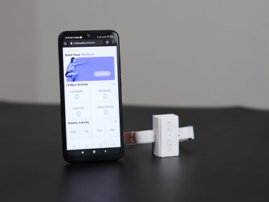
Introducing GetFit, your ultimate health and workout partner. GetFit is an easy-to-use, teachable fitness tracker with the capability of detecting an endless variety of exercises. Powered by Arduino Nano 33 BLE Sense and Edge Impulse, it is a completely open-source project.
Features- Can Count unlimited exercises
- Fully open source
- Teachable
- Rechargeable
- Calorie Burn Estimation on daily and weekly basis
1 / 2 • Arduino Nano 33 BLE Sense

Arduino Nano 33 BLE Sense

Pin Out
For doing this project we are using, Arduino nano 33 ble sense. It's a 3.3V AI-enabled board in the smallest available form factor. It comes with a series of embedded sensors.
- LSM9DS1 (9 axis IMU)
- LPS22HB (Barometer and temperature sensor)
- HTS221 (relative humidity sensor)
- APDS-9960 (Digital proximity, Ambient light, RGB, and Gesture Sensor)
- MP34DT05 (Digital Microphone)
Here we are utilizing the 3 acceleration channels of the LSM9DS1 sensor for counting the activities.
It is a very hard task to recognize the activities using rule-based programming, as people don't perform activities in the same way every time. But machine learning can handle these variations with ease.
To create a machine learning model, you would traditionally use a framework like TensorFlow or Scikit-learn on top of a high-level language like Python. There are a lot of benefits to still learning some of these frameworks, but here we're going to use a tool called Edge Impulse as it just makes model training much easier.
Fortunately, the Arduino Nano 33 BLE Sense is fully supported by Edge Impulse.
Edge Impulse
Using Edge Impulse you can quickly collect real-world sensor data, train ML models on this data in the cloud, and then deploy the model back to your Arduino device. From there you can integrate the model into your Arduino sketches with a single function call.
This documentation contains "How you can get started with Edge Impulse and BLE Sense board"? And also the sample machine learning projects. Don't forget to try, if you are a beginner in this field.
Data acquisition
Data is an unavoidable part of the machine learning model, for the data acquisition and model generation head over to the edgeimpulse.com.
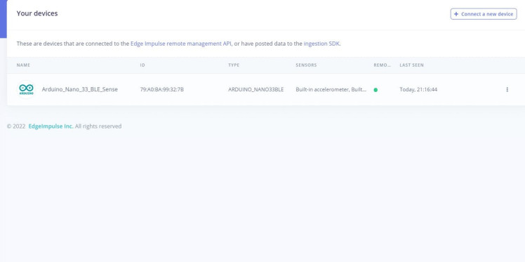
Make sure your device is connected to edge impulse like this.
In the data acquistion tab you can see this data sampling window. These are our data sampling parameters.
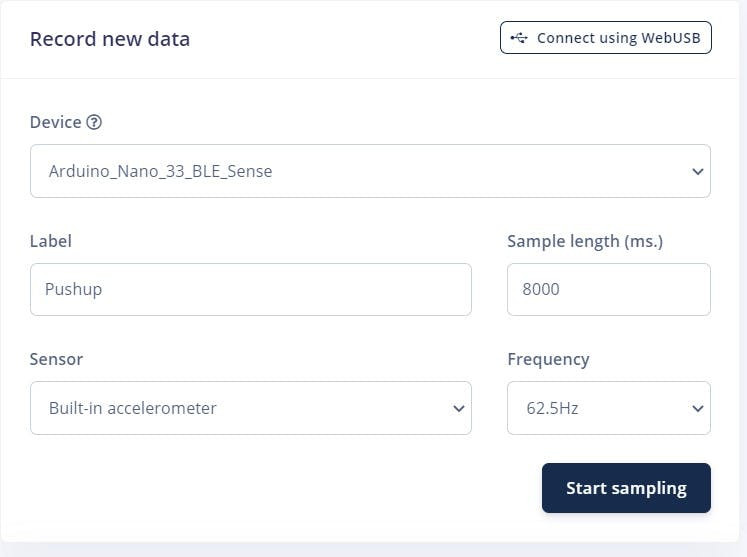
Sample length : How much time we capture the motion? Here we are used 8s for collecting the data. We can only repeat the motion twice or thrice in this time.
Label : Which motion you are trying to capture?
Frequency : The frequency in which data coming from the sensor, here we used 62.5 Hz to get more data.
Sensor : The sensor to be used for data collecting.
Feel free to play with this. When you are doing data sampling you should be very carefull about the labels.Please specify the correct label when you are going from one motion to another motion. In this prototype, we are only counting the pushup, squats and Arm circles as the motions. You can also add your own motions.
For training, we attached the Arduino to my arm with a couple of wiring ties and a sponge, to make the model very accurate for every activity. Then we started sampling.
1 / 2 • Data sampling setup

Data sampling setup

Me during Data sampling
These are the graphical representaion of activities we have collected. Actually these are raw X, Y and Z data from the accelerometer over the time.
1 / 3
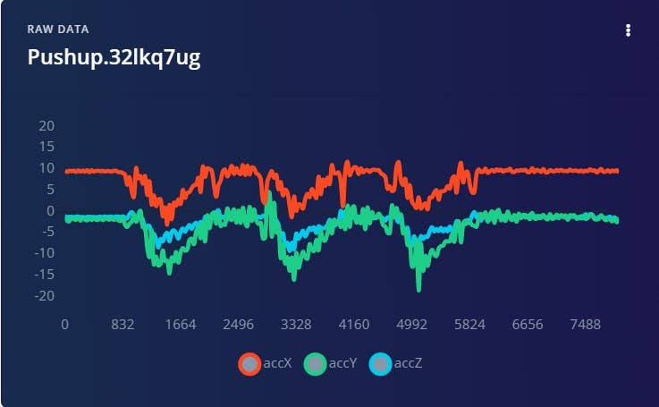
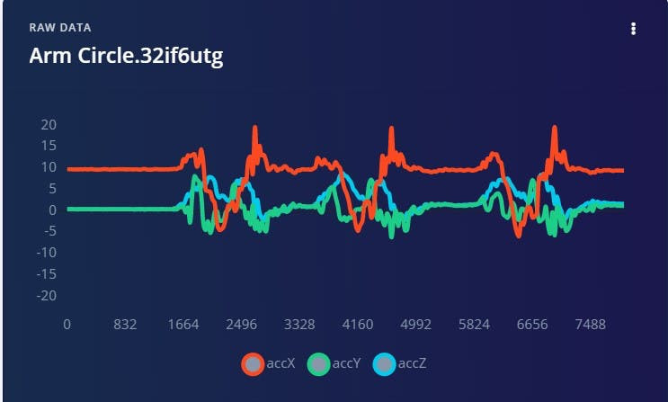
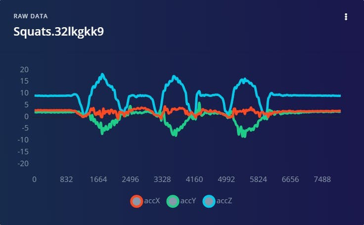
When we analyse the graph of pushups, those spikes clearly shows pushups count. We also made some variations for each motions by speeding up and slowing down.
We have collected around 17min of data. The more data you have, the better your model becomes..Also try to maintain a balanced dataset. Having a balanced data set for a model would generate higher accuracy.
Here we also took the idle state by remaining them stationary at the different starting and ending positions of the motions.
We also performed the split data set for testing the model, That's really a good practicse when analyzing the model. Training data is used to train your model, and testing data is used to test your model's accuracy after training.
1 / 2 • Training data

Training data

Test data
Feature Extraction
Impulse design

Impulse design
Figuring out which features to extract from our data to submit to our model for training and, eventually, inference, is one of the most essential things we can do in machine learning. Rather than picking and choosing some of the raw samples, the edge impulse will combine the samples in a variety of ways to generate unique features that help describe what's going on a particular motion.
We should first create an impulse, which is Edge Impulse's word for a machine learning pipeline, in order to generate features.You should see the first block, which represents your raw data. Here we used window size and window increase as 2000ms, because it perfectly suits for our data.
The processing block refers to our feature extraction method in the edge impulse, Edge Impulse will recommend the spectral analysis block for our motion data, which is what we want.
In the learning slot, we added a neural network cross block.
Although neural networks are fantastic, they have one major problem. They're useless when it comes to dealing with data they've never seen before (like a new activity). Because neural networks only have access to training data, they are unable to assess this. Even if you offer it something entirely different beyond what it's seen before, it'll still fall into one of the four categories. So we also added a Anamoly detection block to find the anomalies in the motions. They will actually stand out in the output.
So we can talk about the feature extraction by considering this raw data of Pushup.
Filtering

Filtering
Here we first applied a low pass filter to remove the noise in the sample. As you can see the raw graph and filtered graph in the above image.
Rather than picking and choosing some of the filtered samples, the Edge impulse combine the samples in a variety of ways to generate unique features that help describe a motion.
So they first calculate the rms value in each axis. We could probably create a classifier model that works very well on just RMS data, as there is a lot of separation between these feature groups. But they take this a step further.
One common technique when looking at vibration or motion data, is to take the Fourier transform of that data to get information about it in the frequency domain.
Edge Impulse takes this even another step further and computes the Power Spectral Density or PSD from the FFT. The FFT can be somewhat misleading sometimes, as the amplitude of the FFT in each bin can vary based on the frequency width of that bin. The PSD helps by normalizing the amplitude to the width of each bin. Rather than feed all of the values in the PSD to the model, Edge Impulse extracts a few important characteristics from it.
The first, is identifying the amplitude and frequency location of the highest peaks of each axis. The second, is they sum all of the values between certain ranges in the PSD. These two actions help describe the shape of the PSD without needing to use all the values in it.
FFT window and spectral power

FFT window and spectral power
Now we have 11 features per axis and total 33 features for the neural network classifier.
This feature explorer window shows the features extracted from the data we have given. As you can see, there is very much seperation between the labels for the rms values itself.
Feature explorer window

Feature explorer window
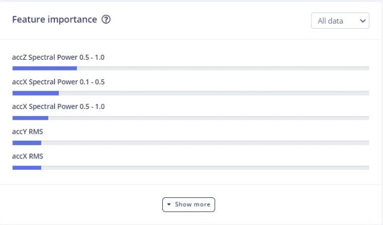
We also calculated the feature importance. The dominant features for these data are.
A neural network is a series of algorithms that endeavors to recognize underlying relationships in a set of data through a process that mimics the way the human brain operates. In this sense, neural networks refer to systems of neurons, either organic or artificial in nature.
Neural networks can adapt to changing input; so the network generates the best possible result without needing to redesign the output criteria
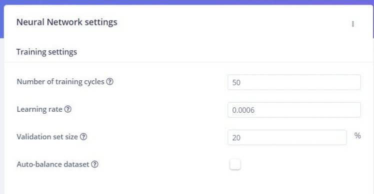
It's time for generating a model by consuming these extracted features. These are our neural network settings.
This is our architecture for generating model.
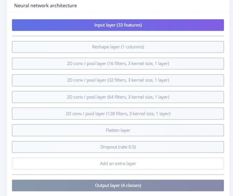
If you don't have any ideas about this, don't worry the edge impulse will automatically suggest the best architecture and settings for you.
By using these settings we made 93% accuracy for the model. It seems to be very awesome. Below image shows the confusion matrix for our model.
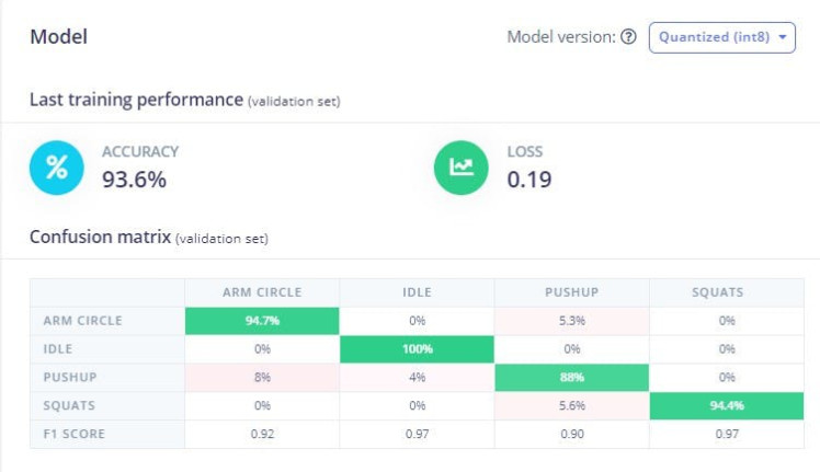
The confusion matrix is very useful, because it helps us to determine the performance of the classification models for a given set of test data. It can only be determined if the true values for test data are known. The matrix itself can be easily understood, but the related terminologies may be confusing. Since it shows the errors in the model performance in the form of a matrix, hence also known as an error matrix.
Anomaly detection
The main intention of anomaly detection is to identify the anomalies during workouts so we will disregard them. We already calculated the feature importance for our data, because they are very significant in anomaly detection.
The edge impulse actually uses K-means clustering for the anomaly detection. This method looks at the data points in a dataset and groups those that are similar into a predefined number K of clusters. A threshold value can be added to detect anomalies: if the distance between a data point and its nearest centroid is greater than the threshold value, then it is an anomaly.
anomaly detection block with prominent features

anomaly detection block with prominent features
The below image shows the anomaly explorer window, When we tried to classify the pushup motion(test data). As you can see the data is enclosed in the cluster. For the anomaly the data points will be outside the cluster.
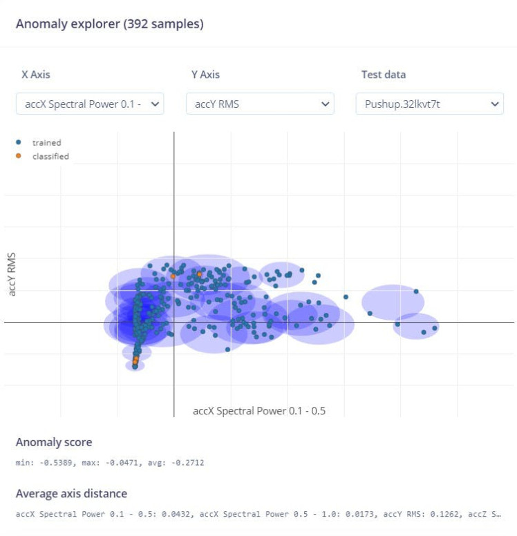
One of the interesting facts is that, the average anomaly score for our data is always negative value. We will consider this fact in the code.
Modeltesting
It's time to validate our model with the test data and see how it performs on the new data.
Model Testing tab

Model Testing tab
It is classifying the test data very well, we have a 87% accuracy. We are good to go.
Deployment
Now that you we have our ML model, its time to deploy it with our edge device(Arduino Nano 33 BLE sense). The ML you trained is already optimized for its use with embedded hardware such as microcontrollers. Deploying the ML model to your Nano 33 BLE Sense board is really simple, just navigate to Deployment on the left menu.
In the Create library section, click on Arduino library and then, on the bottom, click on the Build button. This will start a process where Edge Impulse creates a library for your Arduino board that has the ML model you have trained. When the building process is done, your browser should start downloading the generated library.
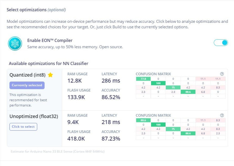
In Edge impulse there are options for selecting the optimizations for NN classifier. By selecting the suitable one, we will be getting better on device perfomance. The surprising fact is that, the Edge impulse will recommend the best one for our purpose. By enabling the compiler we will get same accuracy with less memory.

For sending the data to the cloud we are utilizing the Bluetooth low energy of 33 BLE sense. The device will actually send the data to the phone via Bluetooth and then the phone forwards this data to the firebase and that's our database in this project.
Bluetooth Low EnergyBluetooth Low Energy, BLE for short, is a power-conserving variant of Bluetooth. BLE’s primary application is short distance transmission of small amounts of data (low bandwidth). Unlike Bluetooth that is always on, BLE remains in sleep mode constantly except for when a connection is initiated. This makes it consume very low power and we well get more run time.
That's why we used the BLE for communicating between phone and the Arduino nano 33 BLE sense. In this scenario, the Arduino will act as peripheral and the phone will act as central device
To use the BLE capabilities of the BLE sense, we are using Arduino BLE Library. For getting more ideas, please read the reference here.
Firebase Realtime DatabaseFirebase is a mobile and web application development platform. Firebase frees developers to focus on crafting fantastic user experiences. You don’t need to manage servers. You don’t need to write APIs. Firebase is your server, your API, and your data store, all written so generically that you can modify it to suit most needs. In our project, we use Firebase real-time database to instantly post and retrieve data so that there is no time delay.
To find Firebase Config
- Go to Firebase
- Then go to Settings > Project Settings
- Under Your Apps > SDK Setup and Configuration > Config (Sample given below)
const firebaseConfig = {
  apiKey: "<apiKey>",
  authDomain: "<authDomain>",
  databaseURL: "<databaseURL>",
  projectId: "<projectID>",
  storageBucket: "<storageBucket>",
  messagingSenderId: "<ID>",
  appId: "<APP ID>"
};We have designed a neumorphic companion web app for the device. Neumorphism, or soft UI, is a visual style that combines background colors, shapes, gradients, highlights, and shadows to ensure graphic intense buttons and switches. All that allows achieving a soft, extruded plastic look, and almost 3D styling.
Before starting the workout you need to submit your personal details such as name, age, gender, height, and weight in the personal tab. This info is used in analyzing the workout.
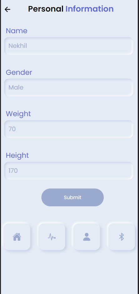
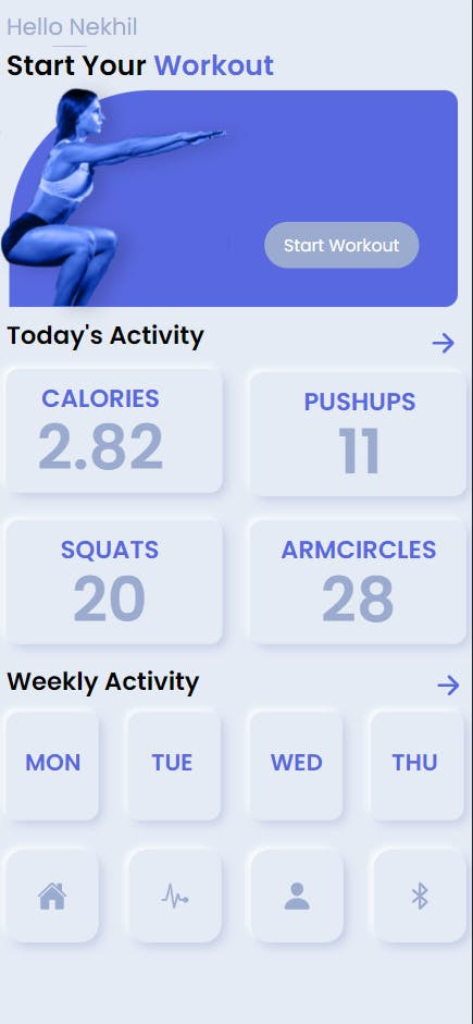
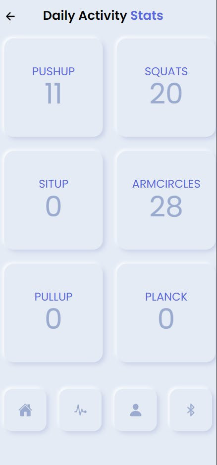
The website is developed using HTML, CSS, and JS and hosted on a free hosting service. Add the Firebase Config in the script.js file and host the code given here and you are good to go.
HardwareSo we can discuss about the remaining hardware setup.
- Lipo battery

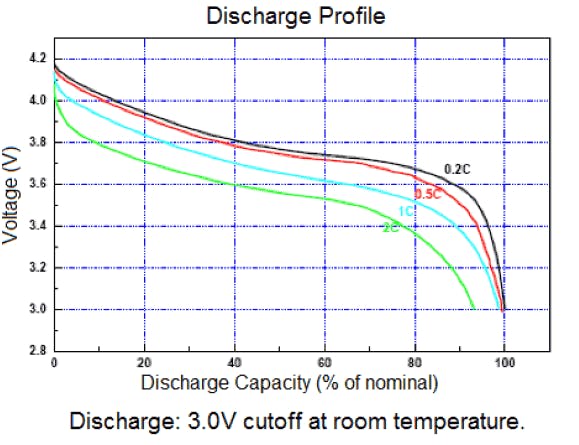
The main advantages of LiPo battery cells are that they have about four times the energy of density of nickel cadmium or nickel metal hydride batteries. They are also very lightweight and pliable.These advantages pointed us to choose a LiPo battery for the device. To reduce the size, Here we used 160 mah battery and that can yield optimum run time for the device. The maximum voltage of the LiPo are 4.2v and that the nominal voltage is 3.7V. The voltage starts at 4.2 maximum and quickly drops down to about 3.7V for the majority of the battery life. Once you hit 3.4V the battery is dead and at 3.0V the cutoff circuitry disconnects the battery. The graph below shows the discharge profile of LiPo.
- DC voltage booster
There are actually two options exist for powering up the Arduino either to give standard 3.3V to 3.3V pin or to give (5-21) Volts to the Vin. In both the cases, we should be very careful.
The VIN (and the USB) goes into a 3.3V switching regulator. This has a minimum input voltage of 4.5V.
When we feed 3.3V from power source directly into the board. We should isolate the output of that regulator from the rest of the circuit by cutting that one link (refer the below image).
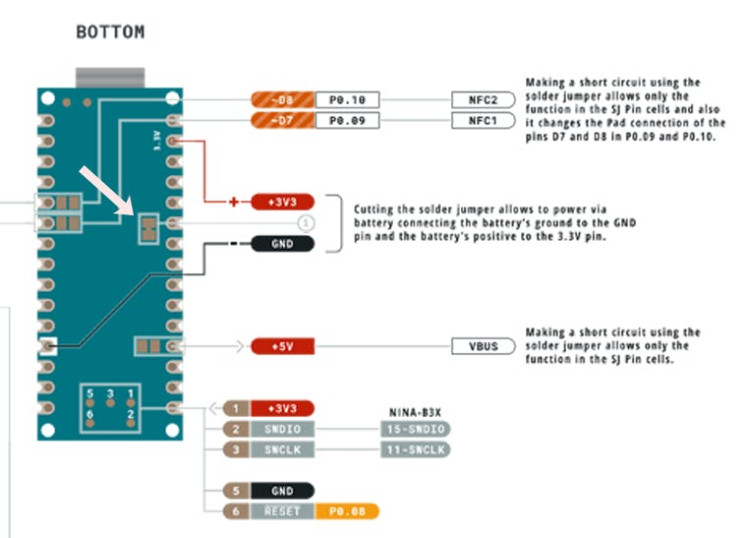
So here we are supposed to give 5V to the Vin of the Arduino, but Lipo batteries can provide up to only 4.2 v when it is fully charged,
To deal with the complication, we are using a voltage boost converter module that provides 5V DC stable voltage output at various input range between 1.5V to 5V.
1 / 2
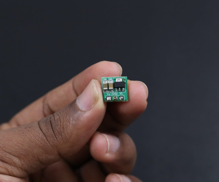

Voltage boost converter
This is the voltage boost converter module provides 5V DC stable voltage output at various input range between 1.5V to 5V. This small tiny circuit boosts the voltage level and provides the amplified stabilized 5V output. For the different input range, it consumes a different amount of current to produce a balanced output.
While using this module one must comply with the following conditions1. Input voltage cannot be greater than the nominal voltage, otherwise, it will burn out the module2. Input power must be greater than the output power, otherwise, the output voltage will be less than the nominal voltage.3. Output load cannot be greater than the nominal load, otherwise, the output voltage will be less than the nominal voltage.
- Starting voltage 0.8V, the output current 7mA
- Input 1-1.5V, output 5V 40-100mA;
- Input 1.5-2V, output 5V 100-150mA;
- Input 2-3V, output 5V 150-380mA;
- Input more than 3V, output 5V 380-480mA;
DC-DC boost converter modules operates at frequency 150KHZ, the typical conversion efficiency is 85%
- TP4056 Li-Ion Battery Charger Module
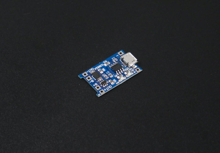
TP4056 module is a linear charger lithium-ion batteries. This module uses the TP4056 Li-Ion charge controller IC and a separate protection IC. They can charge batteries consists of single cells. Most importantly, it supports constant current and constant voltage modes of charging operations. Users can select both modes. This module offers a 1-ampere charging current.
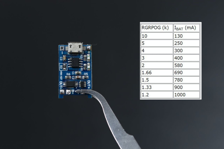
But our battery needs only 170 ma current. The interesting fact of the the module is that, it has a RPROG Current setting resistor(R3). So we can easily adjust the output current by changing that resistor. Below image shows the R3 and its current value.
1 / 2

0805 resistor
The TP4056 charger module have 0805 SMD package, for resistors. We replaced the 1.2K resistor to 10K. Now it can provide 130 ma current for the battery. So our device can be easily charged by means of this module.
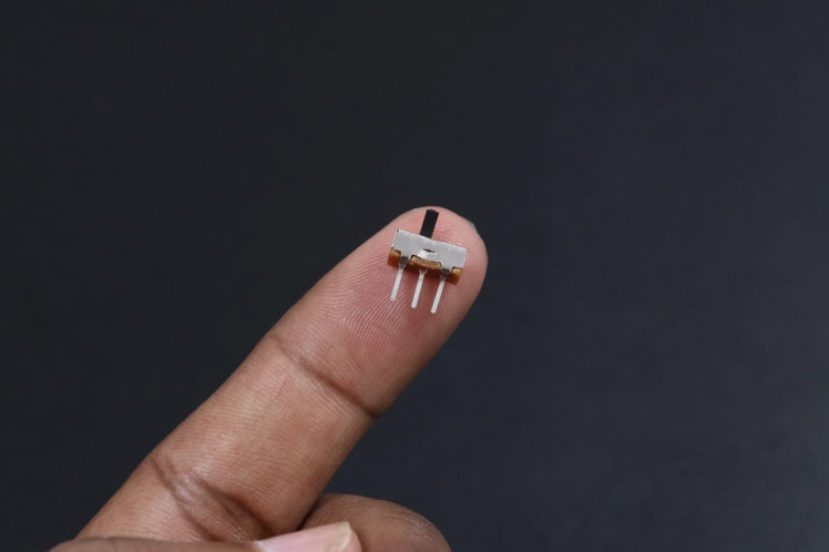
Note : You can also provide 1Amps current to the battery, but it won't last long.4mm SPDT 1P2T Slide Switch used with TP4056 charger module to regulating the current flow between charge controller and voltage booster.

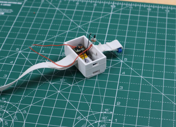
For making the case we have used the Fusion 360, the case actually consist of two parts the main body and the lid. The body and the lid is attached by frictional fit.
Body Only

Body Only
Body with lid

Body with lid
For attaching the TP4056 charger module we actually designed a stand that can be plugged inside. Stand is actually a seperate file, not merged with the body.
TP4056 assembly on stand

TP4056 assembly on stand
The buckles were not found in cheap amount in stores, that's why we designed that as well.
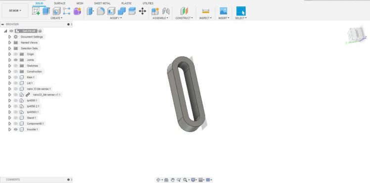
These are the 3d printed parts which we designed. The blue and white color combination makes it more appealing.
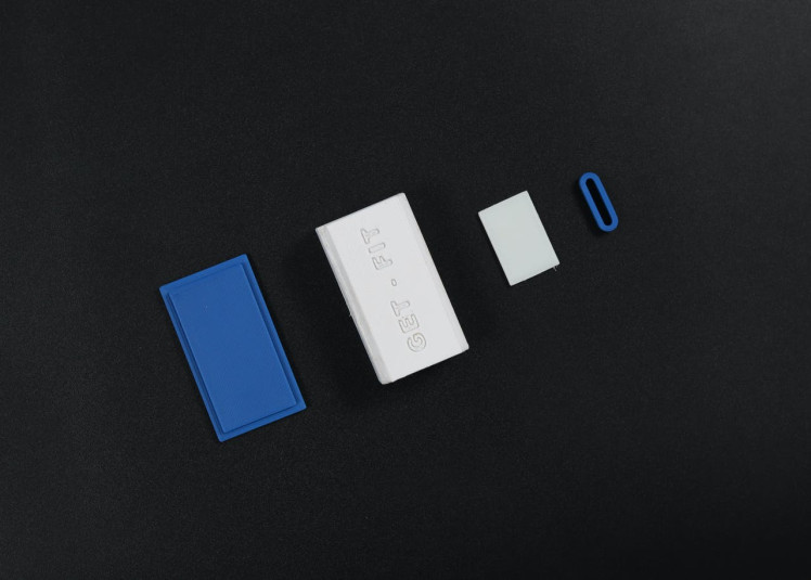
This design is actually meant for the arms, as an armband. The hook and loop mechanism is used here as the fasteners along with this 1/2 inch elastic band. So Any person can wear this band by easily adjusting the strap.
Hook and Loop

Hook and Loop
First we started assembling the strap with the main body.
1 / 3 • 1

1

2

3
Then we started assembling the hardware as per the schematics.
1 / 5
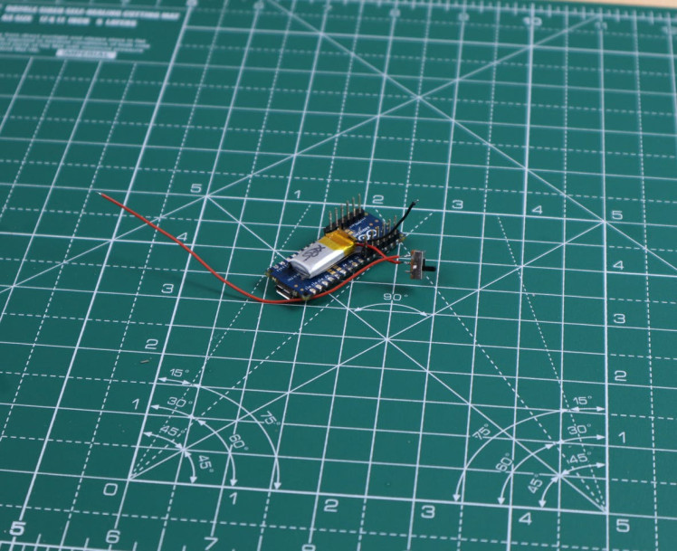
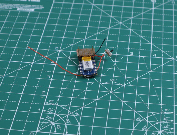
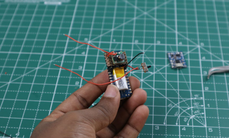
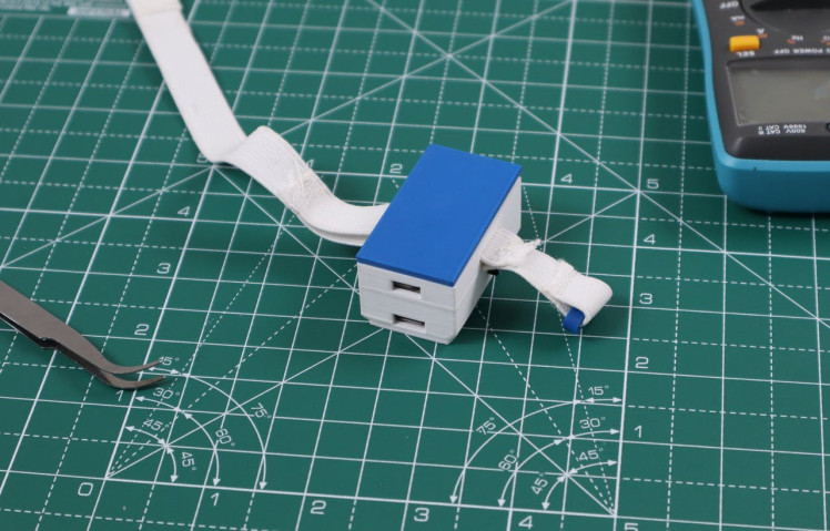
Our Get-Fit is ready to wear now.
Future UpdatesThe following updates will be done on the next version.
- Heart rate sensor will be included
- Galvanic skin response will be included
- More exercise will be added
- Give more clear analytics of your workout
Schematics, diagrams and documents
CAD, enclosures and custom parts
Code
Credits
Related products


Leave your feedback...