
Gas, Carbon Monoxide, Motion And Water Detection

About the project
Detect gas, carbon monoxide, motion and water leaks with this multipurpose project.
Project info
Difficulty: Moderate
Estimated time: 1 day
Items used in this project
Hardware components

Story
I am building this project to play with sensors I've never used before:
- MQ5 gas sensor
- MQ7 carbon monoxide sensor
- a PIR motion detector
- a water leak sensor
I have added certain switches in the firmware to enable you to activate or deactivate individually any of the sensors so you can pick and choose only the ones you really want to use.
Each sensor can generate an alarm and you can use that alarm in any way you want, for instance: an email or a notification on your phone.
The micro-controller
I'll be using a Particle Photon.
The Photon is a $19 (now only $15.20?) tiny Wi-Fi IoT device for creating connected projects and products for the Internet of Things. It's easy to use, it's powerful, and it's connected to the cloud.
All Particle Hardware is designed from the ground up to work with the Device Cloud. The Device Cloud is a powerful set of tools and infrastructure to build, connect, and manage your IoT fleet.
This little beast is packed with many wonderful features. If you haven't, check it out right away!
 https://store.particle.io/products/photon
The gas sensor
I chose this one: Gravity Analog LPG Gas Sensor (MQ5) For Arduino.
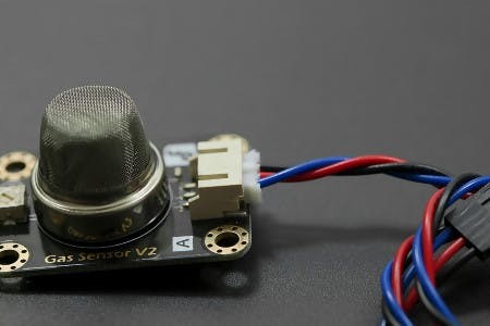 The MQ5 sensor detects gas
The MQ5 sensor is used in gas leakage detecting equipment in consumer and industry applications. This sensor is suitable for detecting Liquefied petroleum gas (LPG), natural gas and coal gas. There is some sensitivity to alcohol and smoke as well.
The sensitivity can be adjusted with an on-board potentiometer.
It uses the standard Gravity interface:
DFRobot Gravity Series is a high quality open-source, modular, plug and play electronics toolkit for everyone to create anything easily. With powerful expansion shields,various professional functional modules with standard interfaces and clear documentations, Gravity Series allows users of any skill level to easily connect and mix to realise ideas or develop projects.
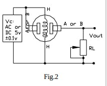
Sensor adjustment to 3v3
Since the analog inputs on the Particle device tolerate 3.3 Volts maximum and the sensor has a 5 volts output we need to adjust it.
peekay123 writes it well on this post:
The sensor has an adjustable load resistor (RL) so you can adjust the maximum voltage output/sensitivity of the sensor. You can power the sensor with 5V and measure the output using a voltmeter (NOT connected to your Particle just yet). Adjust the trimpot to some safe value below 3.3V and then blow some smoke on the sensor to see how it reacts. Adjust the trimpot so the voltage never exceeds 3.3v. Typically, that would be around 4700 ohms or so. Once you are confident that the output voltage will not exceed 3.3v, you can connect it to your Particle.
If possible, disconnect the sensor entirely and measure the set resistance of the trimpot (RL). Then the formula
Vout = 5 * RL / (RL + RS) where RL is the trimpot resistance and RS is the sensor resistance.
You can solve for RS, giving (if I’m correct!):
 Rs = RL * (5 - Vout)
      ---------------
           Vout
You can then get the ppm from the datasheet chart.
 MQ5 pot RL
Connection
NOTE: only once you have adjusted the output to max at 3v3, you can proceed with the connection.
We will be using the analog pin A0 to read the data from this sensor.
 MQ5 goes to A0
Calibration
Please refer to the sensors datasheet for information on how to calibrate this sensor.
Firmware
There is a finite state machine (FSM) for this sensor called mq5StateMachine. If the reading of the sensor goes over the value stated in the variable mq5AlarmThreshold the system will trigger an alarm and the FSM will transition to the alarm state. The line looks like this:
float mq5AlarmThreshold = 2000;
There is this other line in the firmware in case you wanted to deactivate this sensor:
#define USE_SENSOR_MQ5
To deactivate it, comment the line above like this:
// #define USE_SENSOR_MQ5
then re-build and flash.
The carbon monoxide sensor
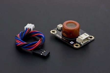
I used a Gravity Analog Carbon Monoxide Sensor (MQ7) For Arduino.
It uses an MQ7 probe to detect Carbon Monoxide (CO) concentrations in the air from 20 to 2000 ppm.
The sensitivity can be adjusted with an on-board potentiometer. The output is analog and proportional to the density of the gas.
; ; 1 / 2 • MQ7 carbon monoxide sensor
Sensor adjustment to 3v3
We need to do the same thing here as we did for the MQ5 sensor. Please refer to the section above for adjustment.
 MQ7 pot RL
Connection
NOTE: only once you have adjusted the output to max at 3v3, you can proceed with the connection.
We will be using analog pin A1 to read the data from this sensor.
 The MQ7 connection is pretty involved!
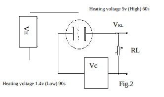
The MQ7 sensor requires switching its input power between 1.4 and 5 volts in cycles of 90 and 60 seconds respectively. This in turn generates a low and high temperature in the sensors internal heater.
From here:
During the low temperature phase, CO is absorbed on the plate, producing meaningful data. During the high temperature phase, absorbed CO and other compounds evaporate from the sensor plate, cleaning it for the next measurement.
So in general operation is simple:
1. Apply 5 volts for 60 seconds, don't use these readings for CO measurement.
2. Apply 1.4 volts for 90 seconds, use these readings for CO measurement.
3. Go to step 1.
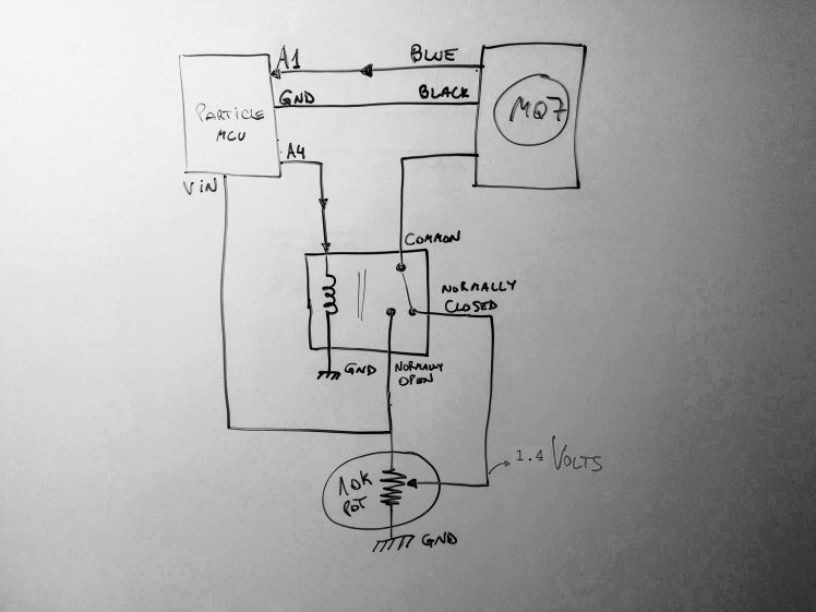
Once everything is connected as in the picture above, calibrate the potentiometer until you read 1.4 volts and connect those 1.4 volts to the Normally Closed (NC) of the relay. Connect the Normally Open (NO) to Vin on the Particle device. The input of the relay must be connected to A4, so A4 as digital output will drive the 90/60 seconds cycle on the relay.
Finally, the output of the sensor goes to A1.
Calibration
Please refer to the sensors datasheet for information on how to calibrate this sensor.
Firmware
There is a finite state machine (FSM) for this sensor called mq7StateMachine. If the reading of the sensor goes over the value stated in the variable mq7AlarmThreshold the system will trigger an alarm and the FSM will transition to the alarm state.
The line looks like this:
float mq7AlarmThreshold = 2000;
There is this other line in the firmware in case you wanted to deactivate this sensor:
#define USE_SENSOR_MQ7
To deactivate it, comment the line above like this:
// #define USE_SENSOR_MQ7
then re-build and flash.
Motion detector
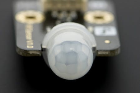
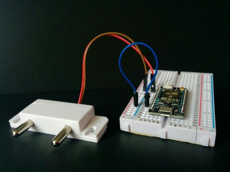
I used a Gravity Digital PIR (Motion) Sensor For Arduino.
This is a PIR (passive infrared motion) sensor designed to work with Arduino and Raspberry Pi. It allows you to sense motion, it is commonly used to detect whether a human has moved in or out of the sensors range. They are small, inexpensive, low-power, easy to use and don't wear out. For that reason they are commonly found in appliances and gadgets used in homes or businesses. They are often referred to as PIR, "Passive Infrared", "Pyroelectric", or "IR motion" sensors.
This PIR (Motion) Sensor can detect the infrared signals from human body or other animals and triggers with movement.
; ; 1 / 2
1 / 2
Some interesting features:
- Detection angle: 100 °
- Detection distance: 7 meters
Connection
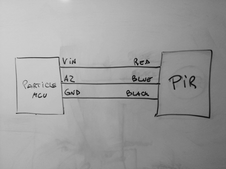 The output of the PIR goes to A2
Water sensor
I've used a regular water sensor with two pins but one can use a twisted pair of wires.
; ; 1 / 3 • water leak sensor
I have another project that uses the sensor and you can read more about it here:
https://www.hackster.io/gusgonnet/water-detection-system-227b08
This is an interesting thought from Zachary:
Water (unless distilled) has the ability to conduct electricity. Theoretically, I could twist two pairs of wire to different lengths, and determine the presence of water based on a short across either pair. Unfortunately, water makes a lousy conductor, so there will be losses in voltage that need to be reconciled in order to measure the presence of the short. Fortunately, we have transistors to do just that, and what's more, we have a Darlington pair, which is a double dose!
That advice is coming from Zachary's project listed here.
Alright, alright, I knew that water could conduct electricity. However I did not know that it was such a bad conductor. That's something that can be improved by adding a couple of transistors with the darlington pair (the MPSA13 transistor Darlington pair).
Connection
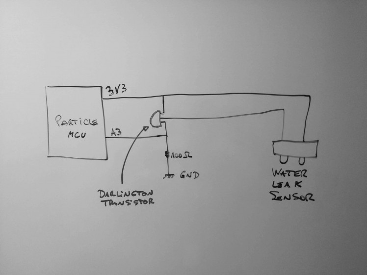 emitter of the transistors goes to A3
Firmware
Finite state machines
The firmware contains few finite state machines (FSMs) to keep track of the status of the sensors (normal or in alarm). One per sensor, plus one for the system level alarm status.
In the case of the MQ5 and MQ7 analog sensors, once the reading is higher than the threshold the FSM transitions to the alarm state and remains there until the reading goes back to normal (under the threshold).
There is a minimum time to stay in the alarm state so the system doesn't transition from normal to alarm state too quickly, and you can change this min value in this line:
#define ALARM_MIN 30000
Debouncing digital inputs
The PIR and water leak sensors are debounced with the algorithm described here:
http://www.kennethkuhn.com/electronics/debounce.c
It reads:
This is an algorithm that debounces or removes random or spurious transistions of a digital signal read as an input by a computer. This is particularly applicable when the input is from a mechanical contact. An integrator is used to perform a time hysterisis so that the signal must persistantly be in a logical state (0 or 1) in order for the output to change to that state. Random transitions of the input will not affect the output except in the rare case where statistical clustering is longer than the specified integration time.
It's pretty solid! I've been using it in many of my projects.
Smoothing analog readings
In this project I used a smoothing algorithm created by Michael Thessel and it's described here:
https://michaelthessel.com/analog-smoothing-library-for-arduino/
The analogReadSmooth() function averages consecutive output readings. You can define how many readings you want to average (window size). Choosing a large window size will smoothen the output considerably but will also slow down detection of actual signal changes. You need to adjust the window size according to your needs when instantiating the AnalogSmooth object.
It's been working great for me.
Alarms
Once the system detects an abnormal situation it will go into alarm state.
Here you can see what will go on in the Particle console:
; ;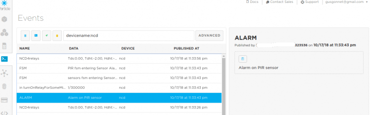 1 / 4 • The PIR sensor is detecting movement
From here, you can configure a webhook to receive notifications on your phone or emails via IFTTT via the Particle channel.
Final notes
I have to admit the MQ7 sensor was harder to work with than I originally thought! It was a nice but unexpected challenge.
But all in all, I learned a lot about the MQ sensors!
Hint: they are complex beasts to manage and require proper reading and calibration.
Need help?
If you require professional help with your projects, don't hesitate to write me a line about your needs at gusgonnet@gmail.com. Thank you!
Check the rest of my projects here!
Code
Credits
Related products


Leave your feedback...