
Esp Solar Tracker - Revolutions

Made by dougal121 / Sustainability / IoT
About the project
Take 3 - Single ESP8266 CPU. Maybe the mix is right this time.
Project info
Difficulty: Difficult
Platforms: Everything ESP
Estimated time: 1 week
License: GNU General Public License, version 3 or later (GPL3+)
Items used in this project
Hardware components


Story
The first and second parts to this story.
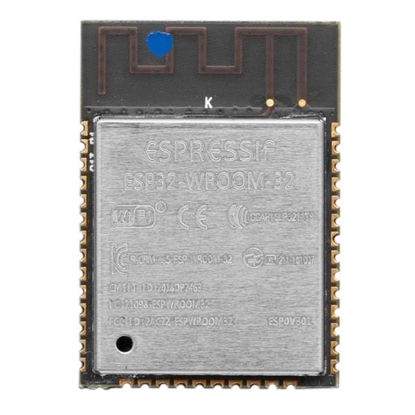
So it's now official, I'm in love with the ESP8266. My god these little fellas can really go like a cut snake on hot sand. So no surprise the the third installment (revolutions) will involve a nodemcu. Now, I have been practicing between drinks so I'm doing a little better coding wise.
So built in reliable WiFi - No problems. Stand alone configuration mode and AP wifi client - No problems. PWM yeah bring it on. In short everything you need to make the solar tracker that has an NTP client and RTC.
So at the end of the second part of the story I was left with a partial success. It all worked but like it just wasn't right. Cant put my finger on what it was but I felt it could be better. I had way better things to do but found myself porting the tracker code to the ESP8266 in the Arduino IDE. It actually took longer to work out the OLED display and wire the items up than it took to port the code.
So not to long after I started I had the smallest tracking computer I had ever made.
1 / 5 • New OLED display for tracker... the most useful thing here is the IP address and time

New OLED display for tracker... the most useful thing here is the IP address and time

Working Solar Tracker Minus the H-Bridge Board - 80ma @ 5V Sweet !!
")
Fire up for the first time from USB port (my laptop is so patient with me)

First run with H-Switch connected - Blue smoke canisters holding !

At 12V power looks good
I'm being much more conscious of power budget this time, taking measurements at each step rather than at the end. I can also put this CPU to sleep if I wish, however not much point if I have enough power or if I need to keep it warm in winter. I'm being mindful that it needs to fit in my 7 AH power budget but this is at 24 V this time. So at present there is still lots of wiggle room.
I have gone for NTP over RTC for the time source. I loved the GPS but overkill and power hungry. The NTP code works great on the ESP8266, one of the most reliable bits, a warm thanks to the person who wrote that example :)
The user interface is much the same as the mega tracker but now has indicators for RTC battery. This interface can operate totally independently of any web services or infrastructure making it ideal for remote installation.
1 / 3 • Main GUI its a wee bit long so I had to stitch the image together

Main GUI its a wee bit long so I had to stitch the image together

This must be one of the best tools I'v integrated into my ESP projects

This can be used via the form or remotely set via a web request
Next task mount it all up and into a the box.
1 / 5 • This time check if it all fits before we go ahead and wire it up - also have access to the micro usb port

This time check if it all fits before we go ahead and wire it up - also have access to the micro usb port

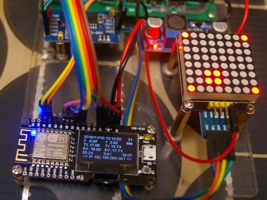
Final Unit with I2C LEd matrix. This has a 3.3V to 5V Level Converter soldered on bottom

Arr Damn, not thinking in 3D properly, the LEd display needs longer legs!

Much better can get the cable in and turn without moving the led display

Ahhh all fits now - seems to work - time for a week of bench test
This time I sort of checked out the layout a bit better before reaching for the drill. I think I might even have my 30% extra space.
This is the first time I've had to use a level shifter as the LED display was 5V only and the rest of the system was cool on 3.3. I actually soldered/sweated the level shifter to the stubs of the pins on the LED board to save wiring and make it more compact.
1 / 2 • 5V goes in A - 3.3V goes in B

5V goes in A - 3.3V goes in B
")
Top side of the board - Very Compact ! :)
So now the one remaining task is work out the OTA updates and get it working with the on farm web server. Well that doesn't turn out to be so difficult. Turns out there is a great web page for this. With surprisingly few lines of code (about 5) you can add an OTA upload server, I shifted this to port 81 so the default page takes you to operations not update. I then just dynamically linked it at the bottom of the main web page as I am a lazy sod who cant be bothered typing :)
So yay for OTA - I don't have to start the power ladder and balance the laptop on my arm at heights while I update the program once the unit is installed.
I also worked out in another project that a "factory reset" for the eeprom data is a good idea, this can be seen on the web interface. Makes initial blank CPU configurations much easier. The I2C scanner is also a very cool tool for working out bus clashes or addressing issues.
Note that I had to change this (ht16k33.h) library, it did a "memcpy" in the constructor which seemed to cause my board to lock up ? Have included the modified one in the code area that works for me, your mileage may vary.
That's about it...All finished...
O yeah, Big thanks to those closest to me for their "special" understanding during these builds.
Update April 2019 - Deployment to South Tower
Finally, a forced break in the traffic. South tower suffered a jack failure, apparently the electric motors don't run long when filled with water. Anyhow jack replaced and finally a reason to deploy the ESP tracker that has been sitting on my desk for 6 months or more. First issue was the H-Switch seemed to saturate above 12V if using valves over 1020 for PWM? So fixed the code so it doesn't, as the FETS where half on and getting mighty hot. Second was I forgot that SSID is case sensitive, DUH. So after a day of patching code, connecting/rerouting cables and testing the box is finally running the south tower pending the sunrise test tomorrow. Oh yeah, this one is set to park in the west to keep water out of the jack!
1 / 3 • Close up of unit mounted along with the motor fuses.

Close up of unit mounted along with the motor fuses.

I tried to get the unit behind the center of the panel to keep it out of the sun

Low cost weathershield for the new jack
The north tower is next and I'm also doing a truck load of re-write on the code so a another unit was born this weeked. Always good to have a second unit to test code on. I will upload the new code to github soon!
Very similar construction for north tower except for the power supply which has a voltage display

Very similar construction for north tower except for the power supply which has a voltage display
A week later and a few "false starts", it's all operating as designed. The IP address has settled to it's reservation and the NTP is doing a query every 24Hrs. It's interesting as you can see the clock drift during the day, only a couple of seconds but it's obvious why the east towers uncorrected clock moves subtly. It's really cool being able to look at the trackers user interface from my office workstation, don't know why it took me so long to get it to this point. Makes me want to return back to where it all started on the east tower and retro fit it with WiFi. Hmm I do have that Dual CPU Uno clone, I wonder ...
Update June 2019
There is now an update that support Alt//Az and Equatorial mounts up on GitHub. It's beta so comments are welcome. Still lots to do like finish the magnetometer calibration page and the wind parking but it's making progress. Thanks to all those who are building and helping with feedback on the program.
1 / 3 • István Szilágyi built this unit for this esp controller / software

István Szilágyi built this unit for this esp controller / software

Controls mounted on back of the panels

I didn't expect numbers like this - opened my eyes a bit more to subtle issues
Have just combined first and third version output programs and eventually tested it on hardware to get the bugs out. Thanks for your patients I've been a bit busy the last few weeks and I did leave the code broken for a while.
Testing Relay Board with Tracker as alternative to PWM - Back to the future ?

Testing Relay Board with Tracker as alternative to PWM - Back to the future ?
There are actually 4 options for output now. PWM, L298 PWM , Relay Active High and Relay Active Low. You will have to buffer and connect as appropriate but these options should cover a wide range of elect to mech configurations.
Update Jan 2020
I finally got around to the mechanical refit of north tower. This was mainly to fix ever growing cracks in the 7 year old steel work. But as the unit was apart a new tracking controller and higher quality solar panels where also fitted.
1 / 3 • Crack propagating out from the pivot.

Crack propagating out from the pivot.

You can see daylight through the RHS on the main gimbal pivot.

Yep to do this meant pulling it all down to remove the center bit
If your fitting panels use a thread release compound on your bolts. If you don't you will be like me and have to wind the heads of a few to undo them. Apparently 5 years is long enough for the stainless bolts to bind solidly in the alloy slot nuts.
So after a few days and some hard work we have.
1 / 3 • All reassembled with 6 x 360W panels instead of the original 8 x 190W

All reassembled with 6 x 360W panels instead of the original 8 x 190W

Looks smaller with 6 panels but the area is actually bigger

The new controller fitted and all working
The mechanicals of north unit are much tighter now, very noticeable during the reload of panels and in the first strong wind. Hopefully this will last 10+ years now.
Before I go, a thank you to Mildura Solar for there help and advice on the high efficiency solar panels. The also found me some compatible racking to match the existing mounting systems.
Schematics, diagrams and documents
CAD, enclosures and custom parts
Code
Credits
Related products


Leave your feedback...