

Downtime Alarm

Made by alistair / Notifications / Productivity / IoT
About the project
A simple system to keep an eye on your server and alert you when it is down.
Project info
Difficulty: Easy
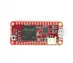
Platforms: Atmel
Estimated time: 2 hours
License: GNU General Public License, version 3 or later (GPL3+)
Items used in this project
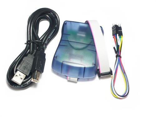
Hardware components

View all
Software apps and online services
Story
Overview
This is a simple entry level hack to monitor a server across the internet and turn on something when there is a problem. Every minute it will ping the server, and if no response is received from it the a relay is turned on (or off) for 10 seconds so sound a horn or turn on a light. It can also be used to monitor your Internet connection.
You will need the components listed to get going. I have used a USB WiFi dongle but you are free to use a WiFi FeatherWing or any compatible USB Ethernet adaptor.
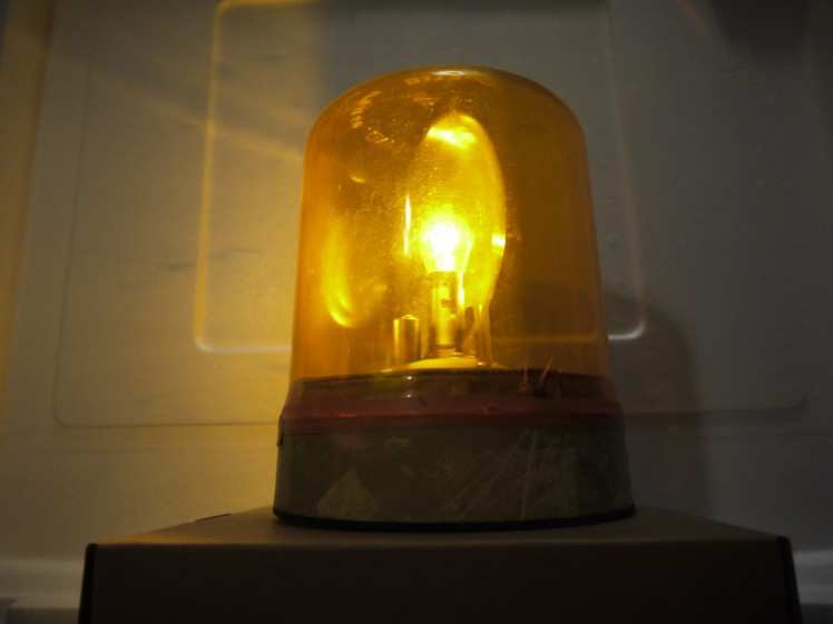
You will also need something to switch, be it a horn, a lamp, or anything else. I have used an old rotary lamp from a scrap yard that was not expensive. You can use can be anything that can be switched by the relay module. I strongly recommend against using high voltage or high current devices as this is not safe. A battery powered set of LED fairy lights will work well.

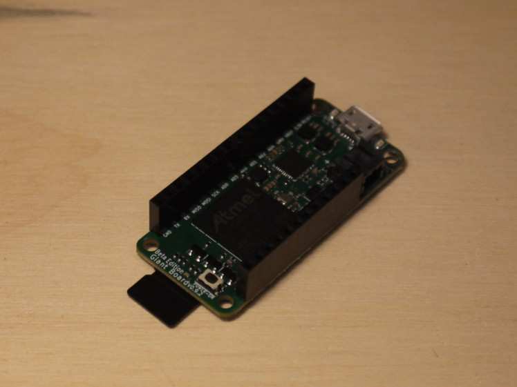
Preparing the Giant Board
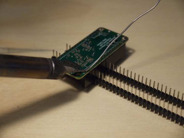
Although we can solder directly on to the Giant Board it would be nice if we could use it again for other projects. Because of this I recommend soldering some header sockets on so we can plug in jumper wires again and again.
If you have not soldered before then you can find many soldering tutorials online. If you think you are not capable of solder then you are mistaken. You can. Everyone can. You might want to experiment on something cheaper first, but if you can solder a resister (and you can) then you can do this. I used some header pins to old the sockets in place (pictured) while I soldered them.
Software Setup
Next we need to install the operating system and set up the software.
To install the operating system follow the instructions on the Groboards web site. Once you have done the you can log in over USB to complete the setup. Also documented on the Groboards web site.
Setting up the network differs on the type of networking device you are using. For my project I used an old "Airlink" based wifi dongle and I followed the Debian instructions to get it working. the instructions you need to follow depends on the dongle you use. Not all dongles work but a number are documented as working on the Groboards forums where you can often find help. This project should also work with the WiFi FeatherWing.
Once you have a working system we can add our code to it. This is really simple. First we need to edit what is called the "crontab" or cron table. When logged in type in "sudo crontab -e" and press enter. You will need to enter the password again and the first time you do this you will be asked what editor to use (I suggest you go with the default of nano).
You will then see the current crontab. Add the following to the end...
- @reboot echo "115" > /sys/class/gpio/export; echo "out" > /sys/class/gpio/PD19/direction; echo "0" > /sys/class/gpio/PD19/value;
- * * * * * if ! ping -c5 www.electromaker.io >> /dev/null 2>> /dev/null; then echo "1" > /sys/class/gpio/PD19/value; sleep 10; echo "0" > /sys/class/gpio/PD19/value; fi
The first line is executed when the device is first turned on or rebooted. It turns on the pin we want to use (AD0) and configures it so we can use it for output and send data to it. The second line is the one that checks if a server can be "pinged" every minute, and if not it will turn on the pin, wait 10 seconds, then turn it off again.
This will monitor the Electromaker server by default. As important as that may be you can change it to monitor your server by replacing "www.electromaker.io " with the domain name or IP address of your machine if you prefer.
Wiring Everything Together
Once we have the software done we can assemble the hardware.
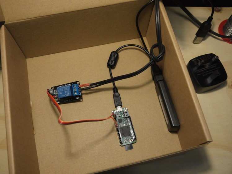
The most complicated part is wiring the relay module. Simply plug one end of a wire in the the 3.3v socket on the Giant Board and the other end in to Vcc on the module. Then repeat for Gnd to Gnd and AD0 to In1. The labels on some relay boards may vary slightly but nut by much.
Next plug the USB lead in to the Giant Board, then plug the WiFi dongle in to it, and finally run it out of the box and plug it in to the USB power supply / phone charger. I have secured everything in to the box with sticky pads. This is optional but be careful nothing shorts out if you do not.
Finally we need to connect in your light or other device. You need to wire in in series with the relay module. Counter intuitively some relay modules will turn on when you turn them off so you will need to use if you light is on when it should be off, or does not turn on at all, then try a different combination of the terminals. You can not damage the relay or your device by doing this.
All done
This is the project finished and working. To test you can use the IP address of your laptop on your local network. When you turn the laptop off it will sett of the alarm within a minute.
You can also monitor more than one server and switch more than one device. Just copy the code again and replace"115" (used to turn on and off the AD0 pin) with "116" for AD1, "117" for AD2, etc, etc...
That is it all done. It is only a shame that it only works when something goes wrong.
Code
Credits
Related products


Leave your feedback...