
Diy Esp32-s3 Thermal Imaging Monitor With Mlx90640

Made by Makerfabs01
About the project
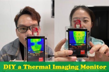
In this project, I will DIY a thermal imaging monitor using the ESP32-S3 3.5" parallel TFT touch screen and the MLX90640 Thermal imaging camera.
Project info
Difficulty: Moderate
Estimated time: 1 hour
License: GNU General Public License, version 3 or later (GPL3+)
Story
It has been a long time since I want to make a thermal imaging monitor in the epidemic for our office. But the array thermal sensor was once very expensive in 2020, as there are huge demands in the COVID-19, that I have to pause my plan, and until recently, I have the chance to do this. Of course, it is good to buy one from the market, but the price is expensive, and actually not so good as my design. Open source both on hardware& firmware.
Supplies
1. The parallel TFT Touch based on ESP32-S3, with resolution 320*240 (Product Link: https://www.makerfabs.com/esp32-s3-parallel-tft-with-touch-ili9488.html)
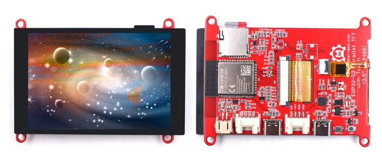
The reason I use this touch is that:
1.) It has a much higher refresh rate than the SPI display, check the comparison video at: https://youtu.be/fXq_TVa0oq4
2.) Based on ESP32-S3, with WIFi, so it can directly transmit the data/result to the local network, for remote monitoring.
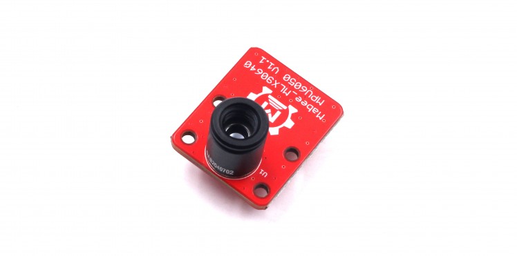
2. And the MLX90640 Thermal imaging camera, which I designed especially for this application. (Product Link: https://www.makerfabs.com/mabee-mlx90640.html)
3. And a set of acrylic cases designed for this, with laser cutting:
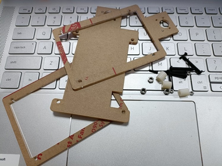
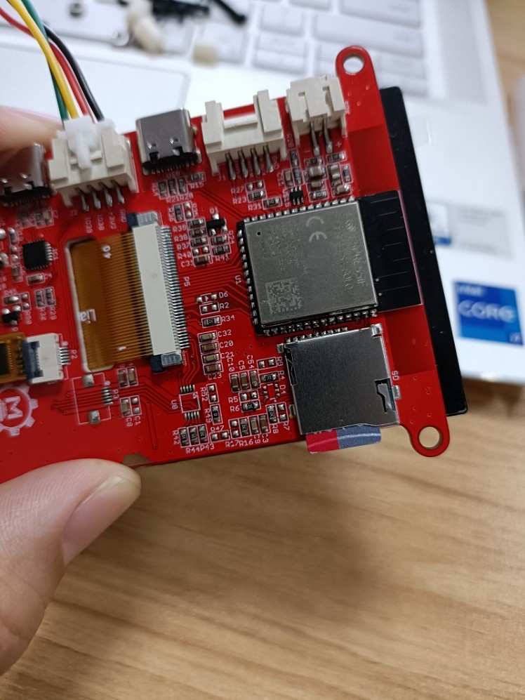
Step 1: Hardware Assembly
The Thermal camera uses I2C for communication with controllers, with I2C address 0x33, while The ESP32-S3 Parallel TFT has build-on connectors(I2C/GPIO) for external sensors, so it gets very easy to connect the Thermal camera to the TFT, by simple plug-n-play cable.

Insert an SD card into the SD slot for data storing.
Step 2: Firmware
Firmware is core work for this application, for the MLX90640, I used the Adfruit_MLX90640 Lib. Besides, as the raw data MLX90640 get is 32*24 data, with noises, that we need to deal with it more with:
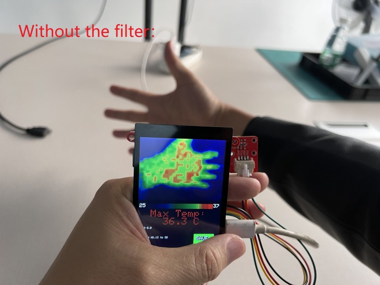
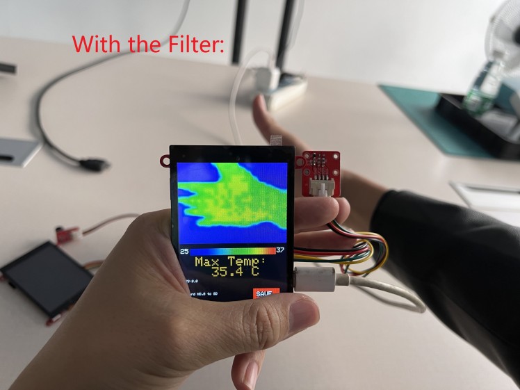
a. Filter the data, to make them smooth for display, or the display will be harsh.
b. Check out the highest temperature among all the raw data. Normally, the highest temperature points it what we are interested in, which tells us if a man is in good/bad health.
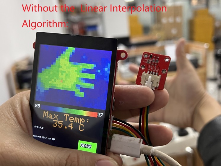
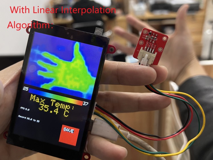
c. Linear Interpolation Algorithm of raw data, to make it not so-pixel looking, and suitable for display(I make it displayed in 320x240 area, 50% area of the display).
1. Filter the temperature data:
Void filter_frame(float *in, float *out)
{
    if (MLX_MIRROR == 1)
    {
        for (int i = 0; i < 32 * 24; i++)
        {
            out[i] = (out[i] + in[i]) / 2;
        }
    }
    else
    {
        for (int i = 0; i < 24; i++)
            for (int j = 0; j < 32; j++)
            {
                out[32 * i + 31 - j] = (out[32 * i + 31 - j] + in[32 * i + j]) / 2;
            }
    }
}
In the filter, the temperature final output was averaged by the input, and thus to create stable& smooth output;
See the contrast of output without/with the filter.
2. Quick sorting out of the temperature, to find out the highest temperature point, and store it at frame[767]:
void qusort(float s[], int start, int end)
{
    int i, j;
    i = start;
    j = end;
    s[0] = s[start];
    while (i < j)
    {
        while (i < j && s[0] < s[j])
            j--;
        if (i < j)
        {
            s[i] = s[j];
            i++;
        }
        while (i < j && s[i] <= s[0])
            i++;
        if (i < j)
        {
            s[j] = s[i];
            j--;
        }
    }
    s[i] = s[0];
    if (start < i)
        qusort(s, start, j - 1);
    if (i < end)
        qusort(s, j + 1, end);
}
3. Linear Interpolation Algorithm of the raw data, to make it better for display, and suitable for the 320x240 display area:
//Transform 32*24 to 320 * 240 pixel
void interpolation(float *data, uint16_t *out)
{


    for (uint8_t h = 0; h < 24; h++)
    {
        for (uint8_t w = 0; w < 32; w++)
        {
            out[h * 10 * 320 + w * 10] = map_f(data[h * 32 + w], MINTEMP, MAXTEMP);
        }
    }
    for (int h = 0; h < 240; h += 10)
    {
        for (int w = 1; w < 310; w += 10)
        {
            for (int i = 0; i < 9; i++)
            {
                out[h * 320 + w + i] = (out[h * 320 + w - 1] * (9 - i) + out[h * 320 + w + 9] * (i + 1)) / 10;
            }
        }
        for (int i = 0; i < 9; i++)
        {
            out[h * 320 + 311 + i] = out[h * 320 + 310];
        }
    }
    for (int w = 0; w < 320; w++)
    {
        for (int h = 1; h < 230; h += 10)
        {
            for (int i = 0; i < 9; i++)
            {
                out[(h + i) * 320 + w] = (out[(h - 1) * 320 + w] * (9 - i) + out[(h + 9) * 320 + w] * (i + 1)) / 10;
            }
        }
        for (int i = 0; i < 9; i++)
        {
            out[(231 + i) * 320 + w] = out[230 * 320 + w];
        }
    }
    for (int h = 0; h < 240; h++)
    {
        for (int w = 0; w < 320; w++)
        {
            out[h * 320 + w] = camColors[out[h * 320 + w]];
        }
    }
}
See the contrast of output without/with the Linear Interpolation Algorithm.
The code is available at: Makerfabs Github.
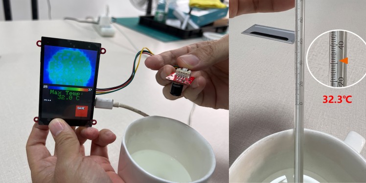
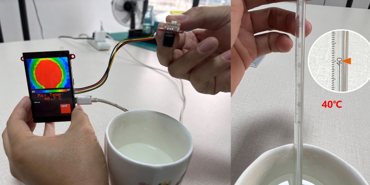
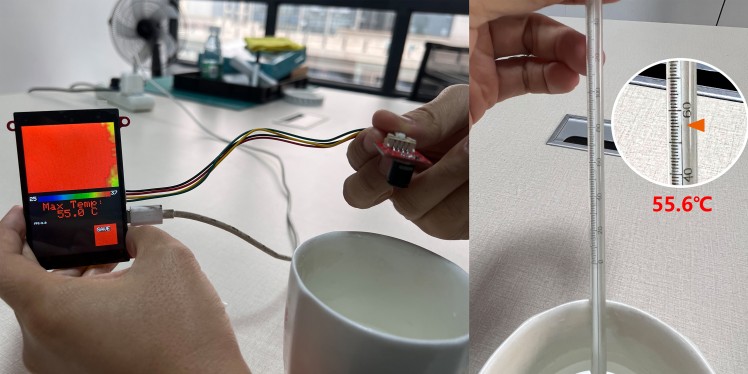
Step 3: Test and Result
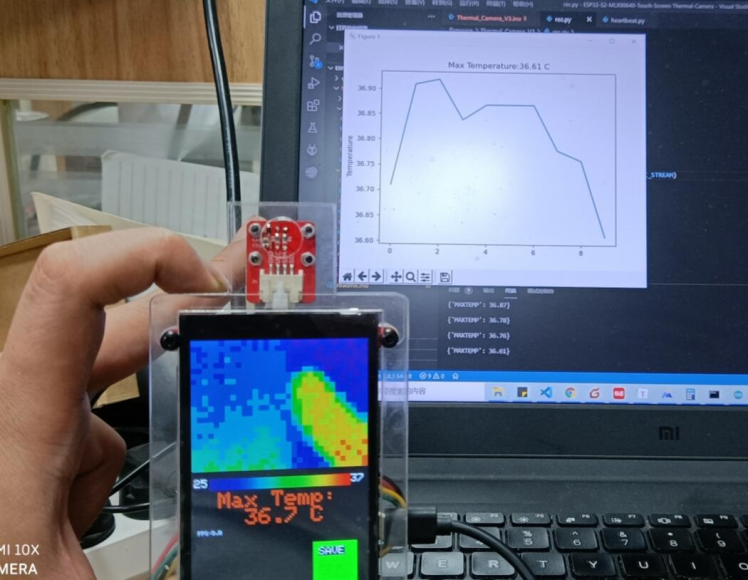
After programming, power the system with 5V power by USB-type C, the display works OK, and the temperature detect:
Step 4: More
There all the temperatures can be stored on the SD card for storing.
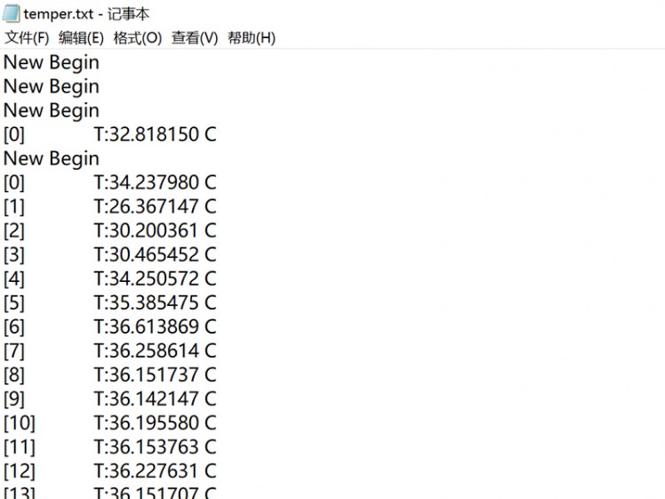
Besides, as the ESP32 WIFI, all the data& pictures can be displayed& stored in local network PC or smartphone, there I made a simple temperature display with Python:
Code
Credits
Makerfabs01
Makerfabs, Turnkey PCB Assemblies | Small Batch PCBA Prototyping | IoT Hardware Engineering.
Related products


Leave your feedback...