
Creating A Wearable Heart Rate Monitor

About the project
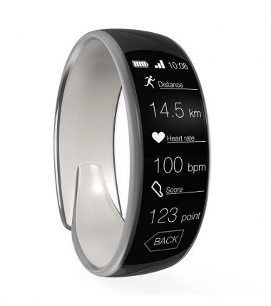
Wearable devices are useful tools that can add convenience to our lives. This project will demonstrate building a wearable HR monitor
Project info
Items used in this project
Hardware components


Software apps and online services
Hand tools and fabrication machines
Story
In recent years, the use of wearable devices has exploded across multiple markets, in large part because of their convenience and the plethora of information they can provide. Activity trackers such as Samsung’s Gear Fit2, medical devices like the Qardio®Arm blood pressure cuff, and even Under Armor’s UA SpeedForm® Gemini 3 Record-Equipped shoes are just a few examples. These devices can provide users with a variety of feedback, including sleep quality, VO2 levels, activity levels, and walking and running cadence, among other data points.
Designing wearable devices requires adding peripherals to sense and display various types of data as well as store and retrieve data in the cloud. This project uses the Pegasus Rapid Development Platform, from Maxim Integrated™ (Maxim), which eases development by integrating key peripherals into the development board along with into Maxim’s 700-MAXREFDES117# heart rate monitor reference design. Rounding out the project technologies, we use an Mbed operating system (OS) for cloud-based programming, Ubidots for cloud services, and Android Studio software for the cloud interface.
If you’re a designer (or a “DIYer”), using these integrated features, reference designs, and cloud programming tools will put you a step ahead at the starting line. The following sections identify necessary project materials and help you program the device, wire the development boards, compile and load the Android app, and transmit data to a cloud service.
Project Materials and Resources
We recommend gathering the following materials and resources before starting this project:
Project’s Bill of Materials (BOM)
Access the project’s BOM on Mouser.com for these required components:
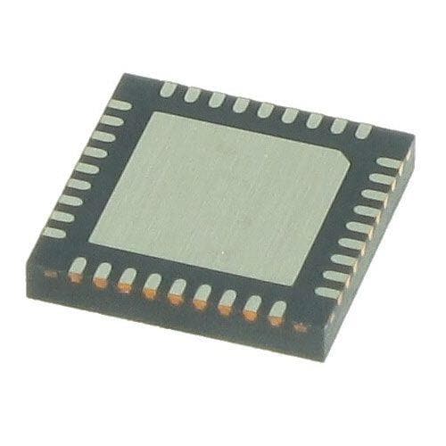
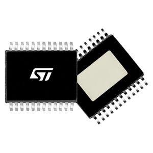
- Maxim’s 700-MAX32630FTHR# development platform, powered by the MAX32630 Arm® Cortex® M4F microcontroller and accompanied by the MAX14690 PMIC battery charge management device
- Maxim’s 700-MAXREFDES117# heart rate monitor with heart rate/pulse oximeter sensor, a step-down DC-DC converter, and logic-level translator
- Lithium Polymer Battery
Project’s Code
Hardware
- Soldering iron
- Jumper wire or regular wire
- Flux
- Header pins
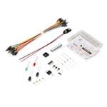
- Breadboard
- Digital multimeter (optional)
- Oscilloscope (optional)
- Expansion peripherals (optional)
Accounts and Software
- A Ubidots Cloud service account
- An Mbed.org account
- Android Studio software
Project Technology Overview
This is an intermediate to advanced project geared towards engineers and DIYers who have programming and soldering experience. We’ve designed this project using the following technologies:
Maxim MAX32630FTHR Pegasus Development Platform
Driving this project is Maxim’s new MAX32630FTHR Pegasus Development Platform (Figure 1). Powered by the MAX32630 Arm® Cortex® M4F microcontroller and accompanied by the MAX14690 PMIC battery charge management device, this platform can assist engineers in rapid prototyping. This feature-packed board sports several integrated peripherals, such as an accelerometer/gyroscope and dual-mode Bluetooth as well as SPI, I²C, UART, 66 GPIO, and much more. The MAX32630FTHR small form factor is compatible with several off-the-shelf expansion boards as well as standard breadboards, presenting countless possibilities. If you are curious about some of the available options, we’ve provided a link under the expansion peripherals.
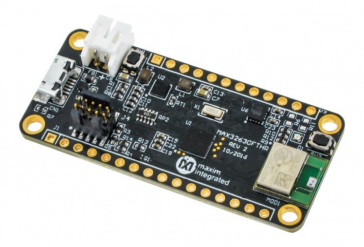
Figure 1: Maxim’s MAX32630FTHR# Pegasus Development Platform is powered by an Arm® Cortex® M4F microcontroller and comes with a PMIC power management device.
Maxim MAXREFDES117# Heart Rate Module Reference Design
Maxim’s popular MAXREFDES117# heart rate module reference design (Figure 2) is tiny yet comes equipped with Maxim’s MAX30102 heart rate/pulse oximeter sensor, MAX1921 step-down DC-DC converter, and MAX14595 logic-level translator. This versatile design can be used within both the Arduino and Mbed platforms for quick integration. Example firmware is available for both platforms and provides the user with a very basic algorithm for determining heart rate and SpO², to help get them off the ground.
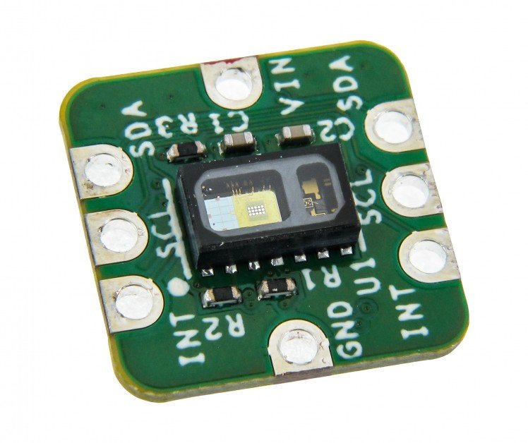
Figure 2: Maxim’s popular MAXREFDES117# heart rate module reference design is tiny yet comes equipped with a pulse rate/oximeter sensor, a step-down DC-DC converter, and a logic-level translator.
Mbed OS for Cloud-Based Programming
Mbed OS gives a convenient cloud-based programming tool to help simplify and speed up the creation of Internet of Things (IoT) platforms. Mbed provides the tools to help collaborate on, contribute to, and publish software for existing code, all while helping to maintain a detailed revision history. Starting with Mbed is as simple as creating an account and finding and selecting the hardware you wish to use. If you have an existing account, you can go to the Mbed repository and import the provided code into your compiler to begin.
Ubidots for Cloud Servicing
Ubidots offers a great jumping-off point for anyone wanting to begin an IoT or cloud project. In addition to having tutorials available for several development platforms, Ubidots offers tutorials on creating an interface between their service and Android apps created in Android Studio. The credit system allows for a simple and affordable way to develop and maintain your projects and offers several methods for obtaining more credits when necessary.
Android Studio for Cloud Interfacing
You’ll need an interface to transfer data from your Maxim board and sensor to the cloud. This can be carried out through a mobile device, such as a tablet or cell phone. For this project, we stayed within the confines of the Android framework and used Android Studio for app creation to aid in visualizing the information our sensor provides.
Developing the Heart Rate Monitor
Working with Mbed
If you have an existing Mbed account, use the Mouser HRM Mbed repository and import the provided code into your compiler.
For first-time users:
Once registered, you can either begin a new project by selecting the highlighted “Compiler” link or by accessing the Mouser HRM Mbed repository and importing the code to the compiler. You can select, review, add, or change platforms within the Compiler screen by clicking the link in the top right corner. You will find several other Maxim products and software samples also supported through Mbed.
Wiring the Board and Reference Design
Wiring the MAX32630FTHR and MAXREFDES117 together requires only a few connections and can be breadboarded to make this easier. To do so, use the following steps:
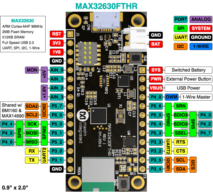
Figure 3: Pin mapping from Maxim MAX32630FTHR# datasheet
Programming the Board
Programming the board is as easy as dragging and dropping a file from one folder to another. The MAX32630FTHR ships with a debug interface used for uploading your code to the board.
To begin:
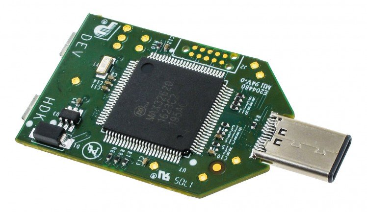
Figure 4: DAPLINK with multiple inputs
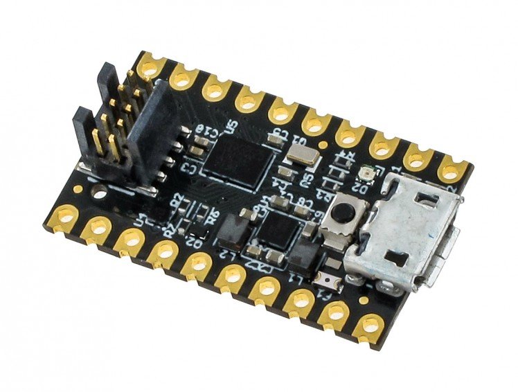
Figure 5: DAPLINK with single input
Once you’ve made your connections and interfaced to the board, you’ll need to compile the code to create the .bin file necessary to program the MAX32630FTHR. From the Mbed Compiler screen toolbar:
The DAPLINK board LEDs should blink rapidly while the programming is taking place. Once completed, the LED will either remain off or blink slowly and steadily on DAPLINK.
Once the board resets, a red LED on both boards will turn on and remain steady.
The Cloud
Once signed in, you should find yourself on the Dashboard page, and from here you can select several options such as view created devices, view available events, review your profile, and see how many credits are available on your account. A few things to note, which will be necessary for any project, are the API tokens, devices, and variable IDs:
Viewing API Tokens
To view the API token, click the “Profile” icon in the top right of the screen and select “API Credentials,” this will drop down a field displaying the API token on the left. The API token is unique to each user and is created when the account is created. This is what stops data transmitted from your device from going to the wrong account.
Adding Devices
Variable IDs are created within each new device when a variable is added. To begin, start by adding a device:
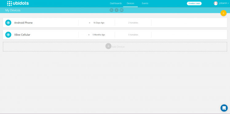
Figure 6: Start with the “Devices” screen.
The “device” represents your project as a whole, allowing you to have multiple projects under one account. The “variable ID” is what helps each created device to identify the specific sensors and inputs assigned to, or built into, your device and what points them to the display in the correct location. This helps you maintain multiple projects and sensors that are separate or shared between devices.
Creating Variable IDs
Creating variable IDs is much like creating the device:
Clicking this new icon will bring up the “Created Variable” screen (Figure 7), which will display several pieces of information along the left-hand side. You can edit much of the information along the left column, which includes: API label, allowed range, unit of measurement, and similar (The important item to note is the ID, which will identify where the data from your program should be placed.).
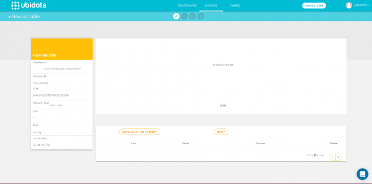
Figure 7: Ubidots “Variable” screen
I highly recommend reviewing the tutorial documentation, located through the drop-down menu by hovering over your “Profile” icon. A lot of very good information is available on topics such as MQTT and HTTP API interfaces along with tutorials on other IoT devices.
Android Studio
You’ll need an interface to transfer data from your Maxim board and sensor to the cloud. This can be carried out through a mobile device, such as a tablet or cell phone. For this project, we stayed within the confines of the Android framework and used Android Studio for app creation to aid in visualizing the information provided by our heart rate sensor.
To save time, I started with the example app, BluetoothLeGatt, which allows you to scan for available Bluetooth devices, connect to those devices, and see the resources available. This can give you a good example for building your own Bluetooth-enabled apps (if you choose to go that route). Ubidots also gives a tutorial on connecting and sending data through the app to their service, which I recommend reviewing for instructions on where to put your API and variable tokens.
Importing the Code
(Note: Remember to change the token keys before building your program, as discussed earlier. If the keys are not updated before building, your data will not be displayed on Ubidots.)
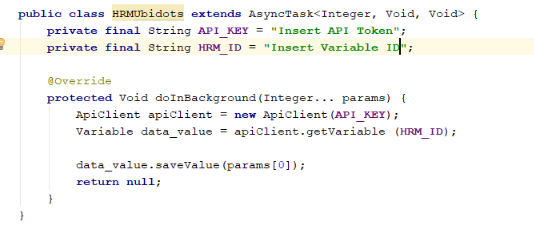
Figure 8: Android Studio Ubidots API token code
Building the App
To test and debug code, you can:
- Build an app to sideload to your device. Use this option if you don’t plan to modify the code beyond updating the API and variable tokens.
- Use the “Developer’s” option. Use this option to enable USB debugging. This will also allow you to use your phone or tablet as a virtual test bed by plugging it directly into the PC you’re programming on. By a web search or through tutorials in Android Studio, you can find instructions on how to enter the “developer mode.”
If you decide to use a device as a development tool, you can simply hit “Run” from the menu bar and select your device to begin building and running the app. Once loaded, the app should appear on your selected device. (Note: You can’t run this app from a virtual device, because Bluetooth is not supported.)
If you plan to simply sideload, you will need to first build the code by selecting “Build,” then “Build APK(s).” This will create a new file, which you can then copy to your chosen device to install.
Even though sideloading the app is an option that works well if you don’t plan to make changes to the software, I do recommend using a device of your choice as a test bed. Using a device in “USB debug mode” will allow you to update, rebuild, and run your code repeatedly, which can be very useful in programming and debugging.
Putting It All Together
Once you’ve had an opportunity to load the app and launch it, you can see a “Scan” icon in the top-right corner that will allow you to scan for any Bluetooth devices in range. If you’ve wired and programmed the MAX32630FTHR and MAXREFDES117 correctly and the device is powered on, you should see a device labeled HRM in the list of devices that populates.
Ready to see the results?
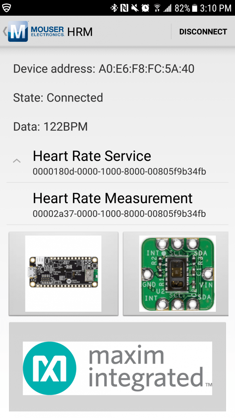
Figure 9: When you select “Heart Rate Measurement,” you’ll see data start to populate the screen.
If you’ve updated the code to include the correct API and variable tokens, you should now be able to log into your Ubidots account and view available data within the device, through the “Device” tab.
You can now create a dashboard for a quick view of the information in several different formats depending on your requirements (Figure 10). Ubidots has recently released a beta Android app that you can install to view your dashboard and devices, from either a phone or tablet (Figure 11).
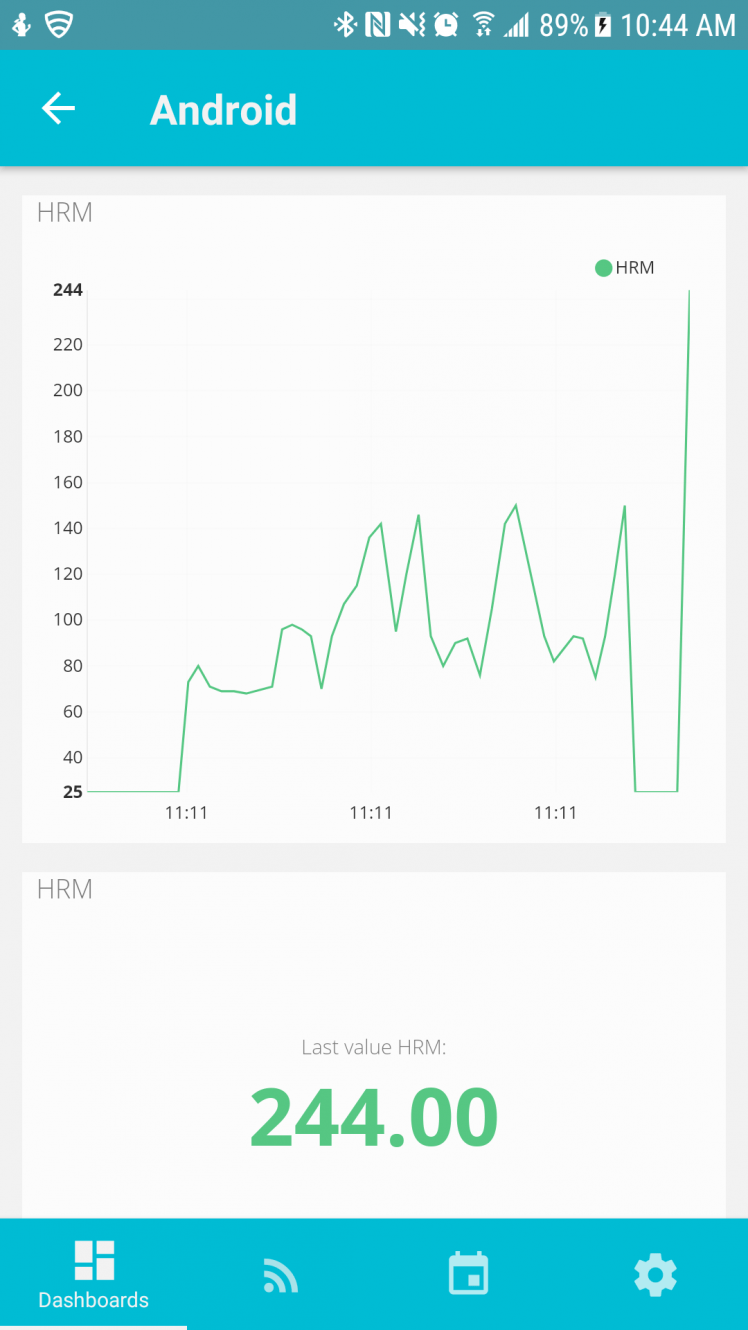
Figure 10: Ubidots Android App Dashboard
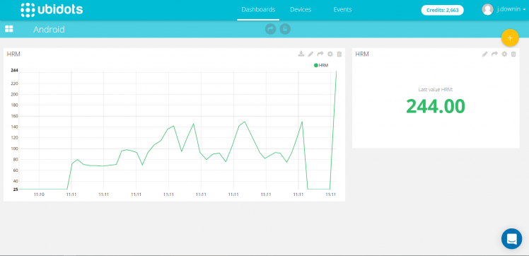
Figure 11: Ubidots Website Dashboard
Conclusion
Wearable devices are useful tools that can add convenience to our day-to-day lives. These devices can provide users with a variety of feedback, including sleep quality, VO2 levels, activity levels, and walking and running cadence, among other data points. What’s more, they can help you monitor your health and communicate to health care providers by sending information, such as daily blood pressure or blood glucose levels.
Designing wearable devices requires adding peripherals to sense, display, store, and retrieve data. The Pegasus Rapid Development Platform has eased development by integrating key peripherals into the development board, and the 700-MAXREFDES117# heart rate monitor reference design is straight-forward to use. Mbed OS, Ubidots, and Android Studio software have rounded out the technologies for cloud-based programming, cloud servicing, and cloud interfacing, respectively.
Schematics, diagrams and documents
CAD, enclosures and custom parts
Code
Credits
Related products


Leave your feedback...