Control an RGB LED w/ Digital Output or PWM ports in Meadow
About the project
Try Meadow.Foundation, a powerful platform to build connected things quickly and easily with Meadow F7 Micro.
Project info
Difficulty: Easy
Platforms: Microsoft
Estimated time: 1 hour
License: Apache License 2.0 (Apache-2.0)
Items used in this project
Hardware components
Story
The intention of this project is to show you how to drive RGB LEDs using Meadow.Foundation by simply instantiating RgbLed or RgbPwmLed objects and use their intuitive APIs that will simplify your hardware solution at the software level.
RGB (Red, Green, Blue) LED lights are diodes that have four legs - one for each of the colors mentioned and one for a common cathode (ground) or common anode (vcc), which is also the longest one.
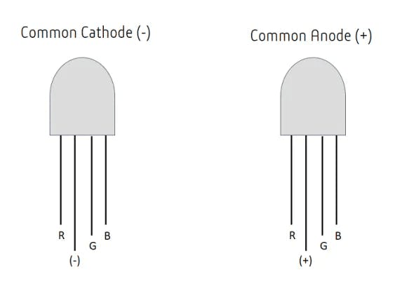
Common Cathode and Common Anode RGB LEDs
If you're new working with Meadow, I suggest you go to the Getting Started w/ Meadow by Controlling the Onboard RGB LED project to properly set up your development environment.
Working with RgbLed
In this first section, we'll work with an RGB LED driver included in Meadow.Foundation specified as RgbLed using three digital input ports. Since this driver uses only digital output ports, we can only set individual pins to high or low, meaning that you can only combine them to make seven different colors.
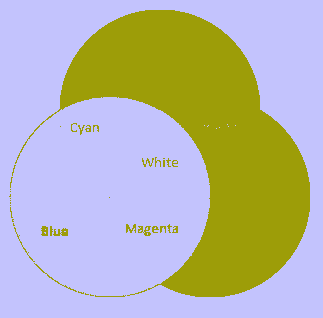
Possible colors with RgbLed
Assemble the circuit
To wire a common cathode RGB LED, connect it like the diagram below, and use 220 ohm resistors to connect the Red, Green and Blue pins with the D02, D03 and D04 pins on the Meadow board. It should look like this:
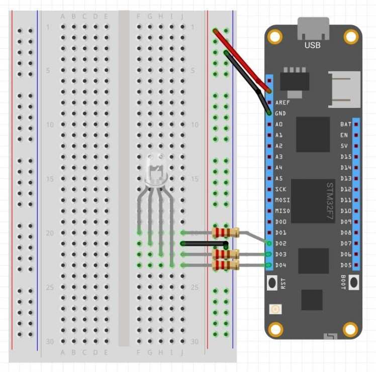
Wiring a common cathode RGB LED with digital output ports
Create a project
In Visual Studio 2019, create a new Meadow Application project, and in the MeadowApp class, copy the following code:
namespace RgbLed_Sample { public class MeadowApp : App<F7Micro, MeadowApp> { RgbLed rgbLed;public MeadowApp () { Console.WriteLine ("Initializing..."); rgbLed = new RgbLed ( Device.CreateDigitalOutputPort (Device.Pins.D02), Device.CreateDigitalOutputPort (Device.Pins.D03), Device.CreateDigitalOutputPort (Device.Pins.D04)); TestRgbLed (); } void TestRgbLed () { Console.WriteLine ("TestRgbLed..."); while (true) { Console.WriteLine ("Going through each color on each RGB LED..."); for (int i = 0; i < (int) RgbLed.Colors.count; i++) { rgbLed.SetColor ((RgbLed.Colors) i); Thread.Sleep (500); } } } } } using System;using System.Collections.Generic;using System.Threading;using Meadow;using Meadow.Devices;using Meadow.Foundation.Leds;
In the MeadowApp constructor, we initialize an RgbLed object, passing three IDigitalOutputPort on pins D02, D03 and D04 by creating them on Meadow doing Device.CreateDigitalOutputPort(IPin pin));
Once rgbLed has been initialized from the constructor it calls TestRgbLed() method, where the app goes inside an infinite while loop in which enters a For loop that iterates through each value of the RgbLed.Colors enum that corresponds to eight possible colors: Red, Green, Blue, Yellow, Magenta, Cyan, White (all pins set to high) and Black (all pins set to low). Each color is set for 500ms (half a second).
Run the project
Click the run button in Visual Studio to see your RGB LED goes through all the possible colors for half a second! It should be similar to the following gif:
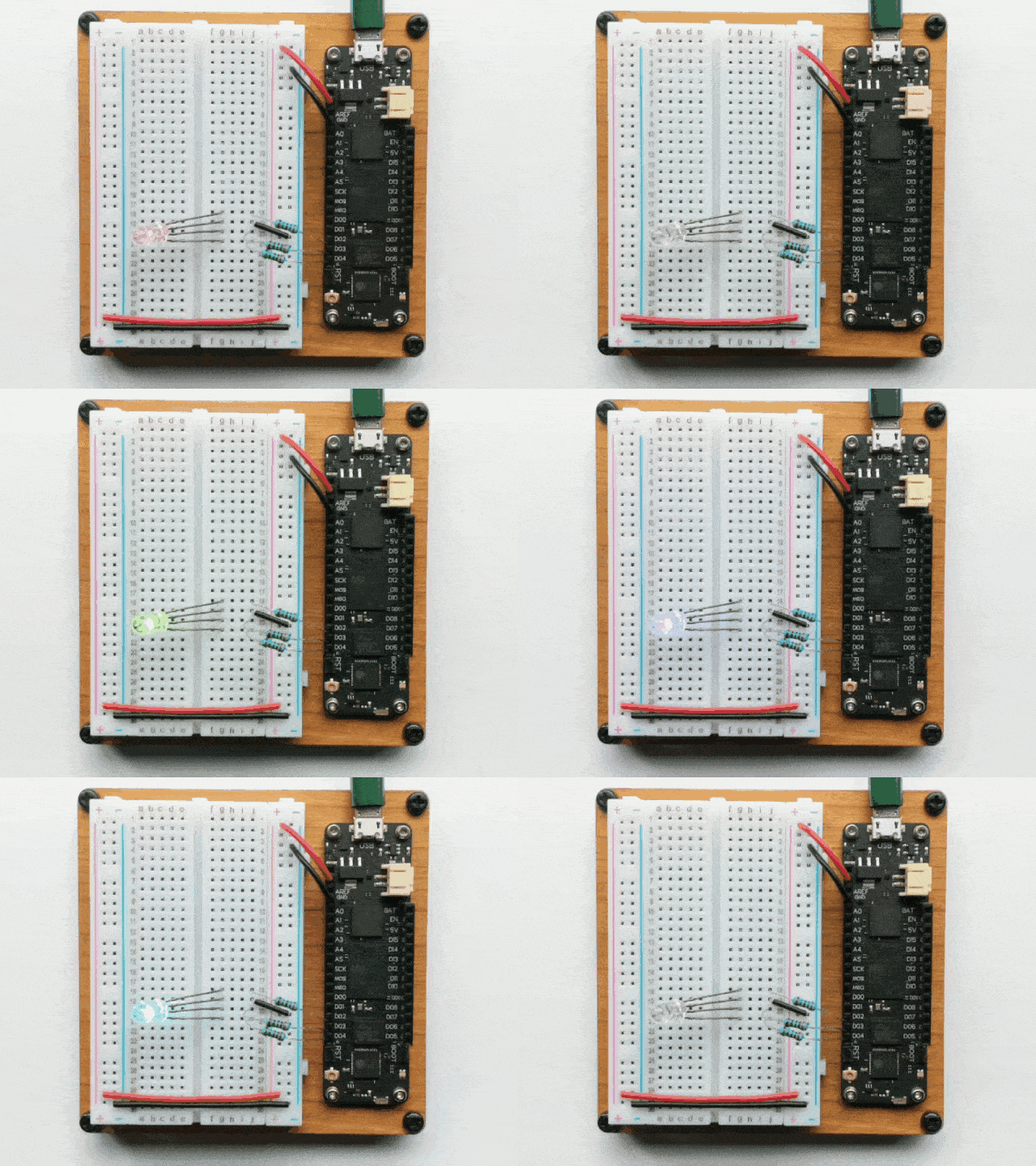
Controlling an RGB LED using Meadow.Foundation.Leds.RgbLed
Working with RgbPwmLed
In the previous section we can see that working with digital output ports, we can make the RGB LED set each pin to High or Low, resulting in a very limited number of colors. What could we do to control the intensity of each pin so we can further expand the variety of colors or make a pulsing animation. For that we'll use RgbPwmLed, another RGB LED driver that is controlled with pulse-with-modulation capable ports.
Important Note: Meadow only supports PWM ports from pins D02 to D13.
Pulse With Modulation is a way of controlling voltage digitally to emulate an analog signal. Meadow boards generate this signal as a square wave. The two key parameters under the control of the developer are the frequency and duty cycle. You can read more here.
In the above diagram, the time where the signal is high is the same as the time where the signal is low. The percentage of time the signal is on (high) is called the duty cycle. So, in the above, the signal is high 50% of the one cycle and so the duty cycle is 50%.

In the above diagram, the time where the signal is high is the same as the time where the signal is low. The percentage of time the signal is on (high) is called the duty cycle. So, in the above, the signal is high 50% of the one cycle and so the duty cycle is 50%.
Assemble the circuit
For this section of the project, you no longer need the resistors to connect the RGB LED. Make the same connections with jumper or solid core wires.
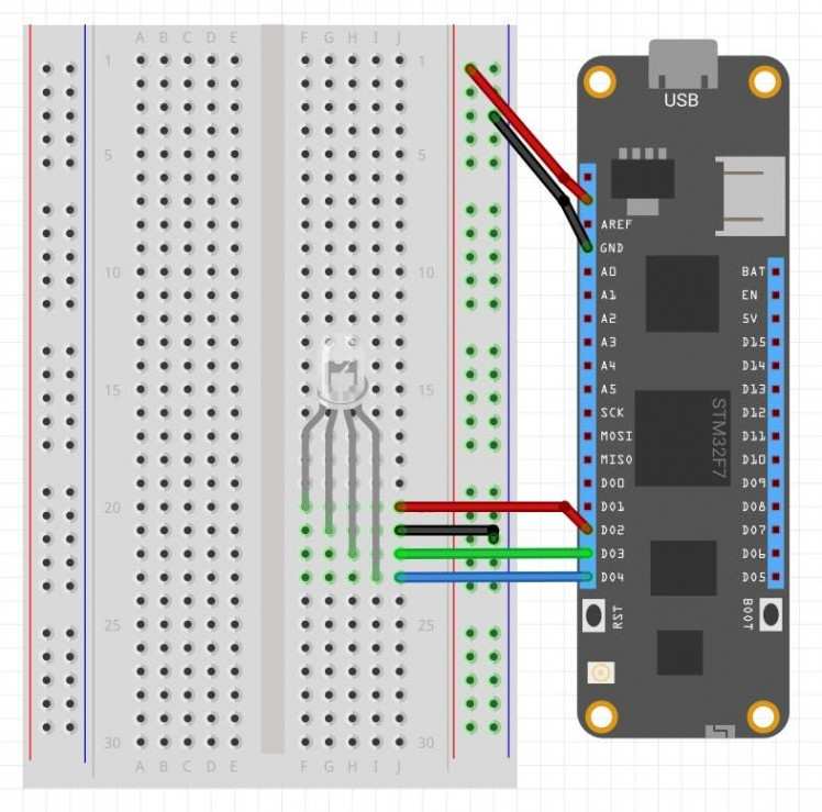
Wiring a common cathode RGB LED with PWM ports
Create a project
In our existing project (or feel free to create a new project), copy the following code:
using System;using System.Collections.Generic;using System.Threading;using Meadow;using Meadow.Devices;using Meadow.Foundation;using Meadow.Foundation.Leds;namespace RgbLed_Sample{ public class MeadowApp : App<F7Micro, MeadowApp> { RgbPwmLed rgbPwmLed; public MeadowApp() { Console.WriteLine("Initializing..."); rgbPwmLed = new RgbPwmLed( Device.CreatePwmPort(Device.Pins.D02), Device.CreatePwmPort(Device.Pins.D03), Device.CreatePwmPort(Device.Pins.D04) ); TestRgbPwmLed(); } protected void TestRgbPwmLed() { Console.WriteLine("TestRgbPwmLed..."); while (true) { for (int i = 0; i < 360; i++) { var hue = ((double)i / 360F); rgbPwmLed.SetColor(Color.FromHsba(((double)i / 360F), 1, 1)); Console.WriteLine($"Hue {hue}"); Thread.Sleep(25); } } } }}In the MeadowApp constructor, we initialize an RgbPwmLed object, passing three PWM on Pins D02 (red), D03 (green) and D04 (blue) calling the Device.CreatePwmPort(IPin pin); method.
Once rgbPwmLed has been initialized, from the constructor it calls TestRgbPwmLed() method, where the app goes inside an infinite while loop in which enters a For loop, where a local double hue is declared and assigned the result of dividing i/360. After that, we call the SetColor(Color.FromHsba(hue, 1, 1)) method on the rgbPwmLed object, and finally do a Thread.Sleep(25) to see all the colors at a moderate speed.
Run the project
Click the run button in Visual Studio to see your RGB LED transition to different colors! It should be similar to the following gif:
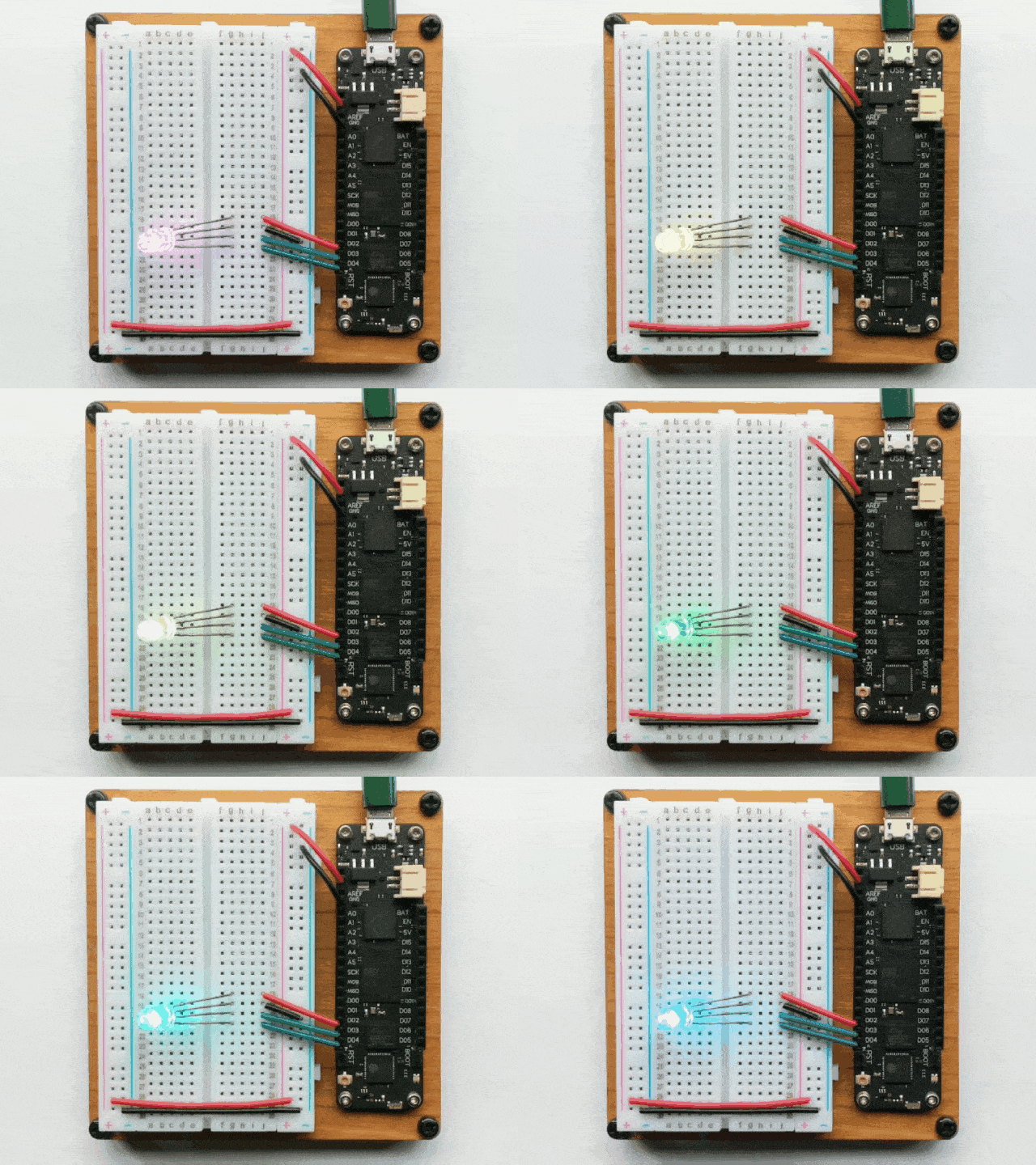
Controlling an RGB LED using Meadow.Foundation.Leds.RgbPwmLed
Check out Meadow.Foundation!
This project is only the tip of the iceberg in terms of the extensive exciting things you can do with Meadow.Foundation.
- It comes with a huge peripheral driver library with drivers for the most common sensors and peripherals.
- The peripheral drivers encapsulate the core logic and expose a simple, clean, modern API.
- This project is backed by a growing community that is constantly working on building cool connected things and are always excited to help new-comers and discuss new projects.






Leave your feedback...